Rolling friction sine mechanism

A rolling friction and sinusoidal mechanism technology, which is applied in friction transmission devices, mechanical equipment, transmission devices, etc., can solve the problems of short service life of the mechanism and low mechanical efficiency of the sinusoidal mechanism, and achieve extended service life, small friction coefficient and high mechanical efficiency Effect

Inactive Publication Date: 2006-09-06
ZHEJIANG UNIV OF TECH
View PDF0 Cites 6 Cited by
  • Summary
  • Abstract
  • Description
  • Claims
  • Application Information

AI Technical Summary

Problems solved by technology

[0004] In order to overcome the defects of low mechanical efficiency and short service life of the sinusoidal mechanism in the prior

Method used


Image

  • Rolling friction sine mechanism
  • Rolling friction sine mechanism
  • Rolling friction sine mechanism

Examples


Example Embodiment

[0016] Embodiment one:

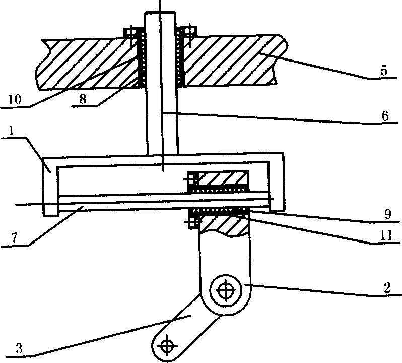
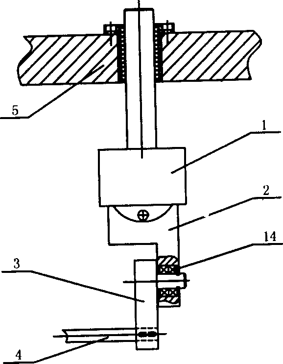
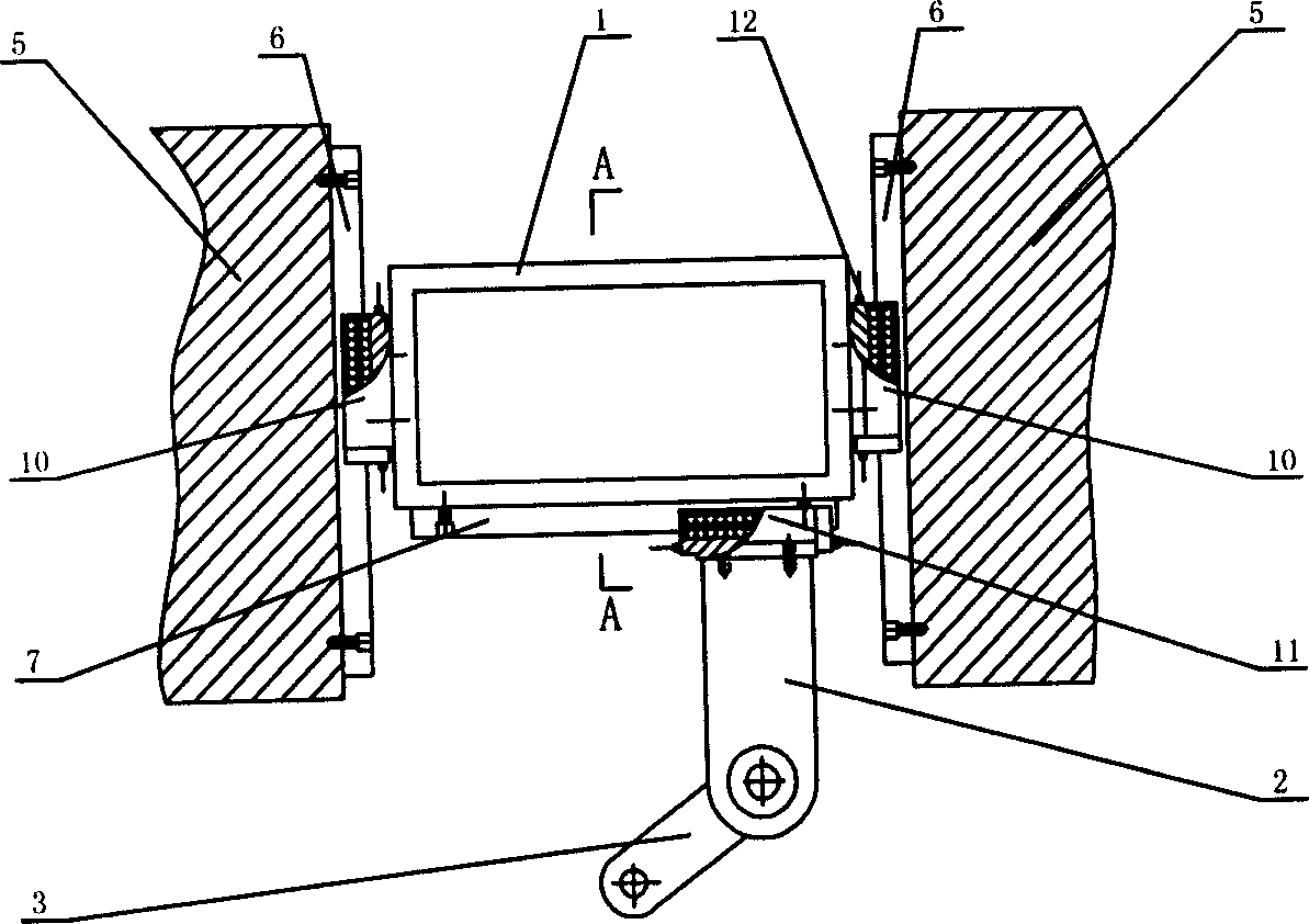
[0017] refer to figure 1 , 2 , a rolling friction sinusoidal mechanism, including a first motion mechanism and a second motion mechanism, the first motion mechanism includes a reciprocating member 1, a first linear guide rail assembly, a slider 2, a rotating member 3 and a rotating input shaft 4 , the slider 2 is slidingly connected to the reciprocating part 1 through the first linear guide rail assembly; the second motion mechanism includes the reciprocating part 1, the second linear guide rail assembly and the body 5, and the reciprocating part 1 and the body 5 pass through the second linear guide rail The components are slidingly connected; the movement direction of the reciprocating member 1 generated by the first movement mechanism relative to the slider 2 is perpendicular to the movement direction of the reciprocating member 1 generated by the second movement mechanism relative to the body 5; the slider 2 passes through the bearing 14 Connected...

Example Embodiment

[0019] Embodiment two:

[0020] refer to Figure 3-5 , the connection mode of the first movement mechanism is: the first guide rail column 7 is fixedly connected to the first reciprocating member 1, and the first guide rail block 11 is fixedly connected to the slider 2. The connection mode of the second movement mechanism is as follows: the second guide rail block 10 is fixedly connected to the reciprocating member 1 , and the second guide rail column 6 is fixedly connected to the machine body 5 . Others are the same as embodiment one.

[0021] The rotary motion provided by the power source drives the rotary shaft 3 to rotate by turning the input shaft 4, and the rotary shaft 3 drives the slider 2 to drive the reciprocating component 1 along the second linear guide component through the first linear guide assembly on the reciprocating component 1. Sine regular reciprocating motion.


PUM


Abstract

The invention relates to a rolling friction sine device, which comprises the first motion device and the second motion device. Wherein, the first one is formed by oscillating motion element, the first straight guide rail, a sliding block, a revolving element, and a revolving input axle, while the sliding block and the oscillating motion element via the first straight guide rail are sliding connected; the second motion device comprises a oscillating motion element, the second straight guide rail and a frame, while the oscillating motion element and the frame are sliding connected via the second straight guide rail. The motion direction generation by the first oscillating motion element is vertical to the motion direction of the oscillating motion element of second motion element; the first and second straight guide rails have sliding rollers mounted inside the sliding grooves. The invention has longitudinal rolling grooves on the working surface, and the roller uses rolling friction, with less friction parameter and high mechanical efficiency.

Description

(1) Technical field [0001] The invention relates to a sinusoidal mechanism (also known as a simple harmonic mechanism) composed of rolling friction pairs. (2) Background technology [0002] A sinusoidal mechanism is a mechanism that converts input rotational motion into a specific reciprocating motion law, wherein the specific reciprocating motion law means that the amplitude of the reciprocating motion output by the mechanism is a sinusoidal function of time. The sinusoidal mechanism should be the core component of the vibration test equipment. However, no sinusoidal mechanism with high friction performance has been seen so far, so it has not been well applied in the test equipment. The vibration test equipment often adopts the law of approximate sinusoidal motion. A reciprocating mechanism (such as a crank linkage) instead. [0003] The existing sinusoidal mechanism has sliding friction, which has defects such as low mechanical efficiency and short service life of the mec...

Claims


Application Information

Patent Timeline
IPC IPC(8): F16H19/02
Inventor 谢伟东王磊汪立明
Owner ZHEJIANG UNIV OF TECH
Why Eureka
Try Eureka