Antennas array calibration arrangement and method

An array and antenna unit technology, applied in the field of devices for controlling signal transmission and/or reception, can solve problems such as cost and space requirements

Inactive Publication Date: 2006-09-06
PROVENANCE ASSET GRP LLC
View PDF2 Cites 24 Cited by
  • Summary
  • Abstract
  • Description
  • Claims
  • Application Information

AI Technical Summary

Problems solved by technology

[0012] The procedure described above is tolerant of the fact that a dedicated calibration devic

Method used


Image

  • Antennas array calibration arrangement and method
  • Antennas array calibration arrangement and method
  • Antennas array calibration arrangement and method

Examples


Embodiment Construction

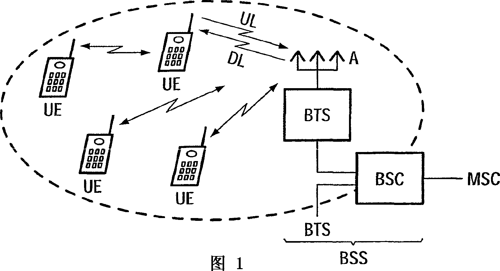
[0027] FIG. 1 shows the basic structure of a mobile radio communication system, for example a GSM system. The system comprises a central mobile switching center MSC which is connected to the public switched telephone network PSTN and to other MSCs. A plurality of base station controllers BSC are connected to one MSC, which also coordinates the sharing of the radio resources provided by the base station BTS (Basic Transceiver Station). The base station BTS respectively transmits signals in the downlink DL to the user equipment UE located within the range covered by the base station BTS, and receives signals from the user equipment UE in the uplink ULS. In Fig. 1, the base station BTS comprises an antenna array A consisting of a plurality of antenna elements. Such antenna arrays, sometimes referred to as smart antennas depending on the configuration, are used for beamforming of signals transmitted to a single user equipment in order to reduce interference caused by signal trans...


PUM


Abstract

According to an aspect of the present invention, an apparatus for controlling signal transmission and/or reception in a radio communication system is disclosed, which includes: Transceiver devices (TX, RX), wherein at least one of said transceiver devices (TX, RX) is additionally connected to a calibration antenna for sending to and/or from said antenna elements (#1...# n) transmit and/or receive test signals; at least one calibration processor for determining variations of said test signals within said transceiver device (TX, RX); and a beamforming processor for converting the determined The variation of takes into account the beamforming and/or the determination of the direction of arrival for the radio signals transmitted and received by said antenna elements (#1...#n), respectively.

Description

field of invention [0001] The invention relates to a device and a method for controlling signal transmission and / or reception in a radio communication system, especially for use in a base station of a mobile radio communication system. Background of the invention [0002] In radio communication systems, signals are exchanged between radio terminals and base stations via so-called radio interfaces or air interfaces. A radio terminal is usually a mobile or stationary user terminal (UE-User Equipment), while a base station (NB-Node B) is an access station associated with a land-based communication network. Examples of known radio communication systems are: second generation digital mobile radio communication systems such as GSM (Global System for Mobile Communications) based on TDMA (Time Division Multiple Access) and offering data rates up to 100 kbit / s, and third generation digital mobile radio communication systems Communication systems such as UMTS (Universal Mobile Teleco...

Claims


Application Information

Patent Timeline
IPC IPC(8): H04B7/04H01Q3/26H04B7/06H04B7/08
CPCH04B7/04H01Q3/267H04B7/0615H04B7/0842
Inventor C·希布利希
Owner PROVENANCE ASSET GRP LLC
Why Eureka
Try Eureka