Stator of motor

A technology of motor stator and stator iron core, which is applied to electromechanical devices, electrical components, electric components, etc., can solve the problems of coil weight limitation, reduce the number of turns of the coil 26, etc., and achieve the effect of reducing weight and improving lamination coefficient.

Inactive Publication Date: 2006-09-13
LG ELECTRONICS INC
View PDF0 Cites 2 Cited by
  • Summary
  • Abstract
  • Description
  • Claims
  • Application Information

AI Technical Summary

Problems solved by technology

[0014] However, as described above, in the stator 20 of the conventional motor, since the structure of the neck portion 23 of the tooth 24 is limited by the lamination factor, the number of turns of the coil 26 is reduced and the weight of the coil relative to the coil of the same number of turns is reduced. restricted

Method used


Image

  • Stator of motor
  • Stator of motor
  • Stator of motor

Examples


Embodiment Construction

[0047] Hereinafter, embodiments of the motor stator according to the present invention will be described with reference to the accompanying drawings.

[0048] Various embodiments of the invention may be described. Since the basic structure of the stator is the same as that of the conventional motor, a detailed description of the basic structure will be omitted.

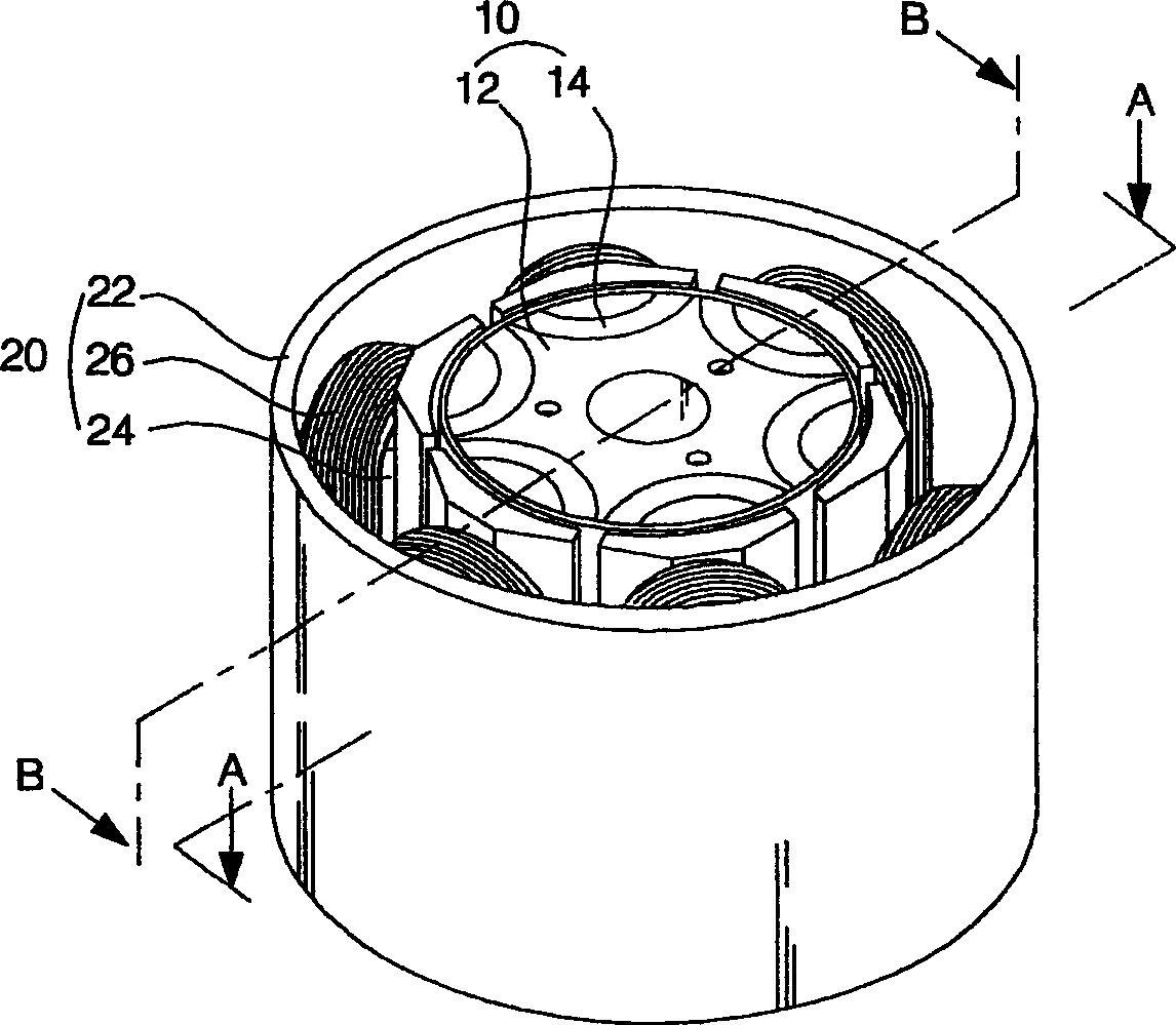
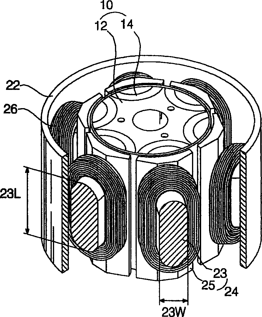
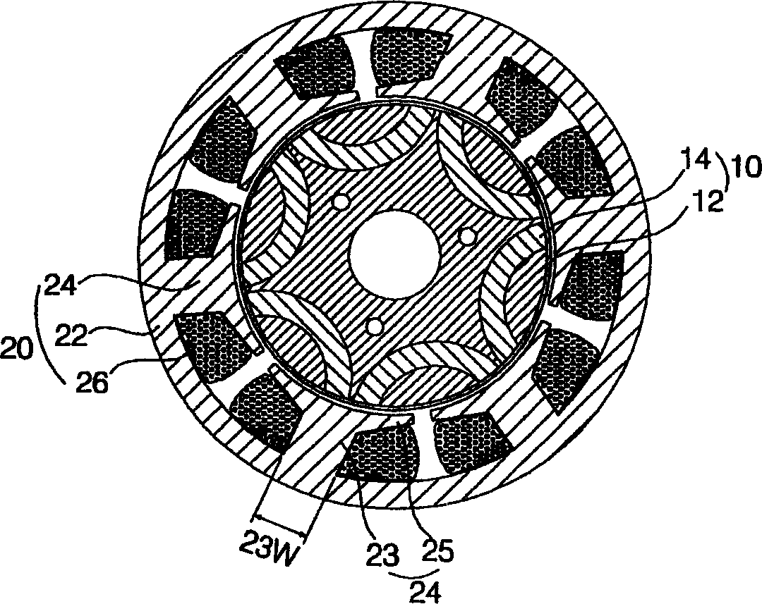
[0049] Figure 7 To illustrate a perspective view of a motor stator according to a preferred embodiment of the present invention, Figure 8 for along Figure 7 sectional view of line C-C, Figure 9 In order to illustrate a partially cut-away perspective view of a motor stator according to a preferred embodiment of the present invention, Figure 10 is an unassembled schematic diagram showing the teeth of the motor stator according to the preferred embodiment of the present invention, and Figure 11 It is a schematic diagram of the manufacturing process of the motor stator according to the preferred embodiment of the...


PUM


Abstract

A stator of a motor includes a ring-shaped yoke, a plurality of teeth radially arranged in a zigzag fashion on the circumference of the yoke, and coils wound around the teeth. Since necks of the teeth are shorter than the yoke and are spaced apart from necks of circumferentially neighboring teeth in the axial direction, lamination factor of windings is enhanced. Moreover, since the necks of the teeth have a circular cross-section, the weight of windings with respect to the same turns of windings can be reduced.

Description

technical field [0001] The present invention relates to a motor stator, and more particularly, to such a motor stator in which the necks of teeth adjacent to other teeth in the circumferential direction are staggered in the axial direction. Background technique [0002] figure 1 To show a perspective view of a conventional motor stator, figure 2 To show a perspective view of a conventional motor stator partially cut away, image 3 for along figure 1 A sectional view of line A-A in, Figure 4 for along figure 2 Sectional view of line B-B in . [0003] Figures 1 to 4 The conventional motor shown in is an inner rotor motor in which the rotor 10 is rotatably mounted in the stator 20 and rotates due to the interaction between the rotor 10 and the stator 20 . [0004] The rotor 10 includes: a rotor core 12 provided in the stator 20 to rotate while maintaining a predetermined gap; and a plurality of magnets 14 embedded in the rotor core 12 in the circumferential direction...

Claims


Application Information

Patent Timeline
Patent Type & Authority Applications(China)
IPC IPC(8): H02K1/14H02K3/18
CPCH02K1/146A41C3/144A41C3/128A41C3/0007
Inventor 沈长昊金炳择李成浩朴镇洙
Owner LG ELECTRONICS INC
Why Eureka
Try Eureka