Electric motor

A technology of motor casing and mechanical energy, which is applied in the direction of electric components, electrical components, electromechanical devices, etc., can solve the problems of wasting space, reducing the stacking coefficient from coil to slot, etc., to improve the stacking coefficient, reduce the amount of coil winding, and reduce the reluctance Effect

Inactive Publication Date: 2006-10-18
MITSUBA CORP
View PDF0 Cites 4 Cited by
  • Summary
  • Abstract
  • Description
  • Claims
  • Application Information

AI Technical Summary

Problems solved by technology

This way, if all the slots have the same shape, there will be wasted space in each slot, reducing the coil-to-slot stack factor

Method used


Image

  • Electric motor
  • Electric motor
  • Electric motor

Examples


Embodiment Construction

[0024] Hereinafter, embodiments of the present invention will be described in detail with reference to the accompanying drawings.

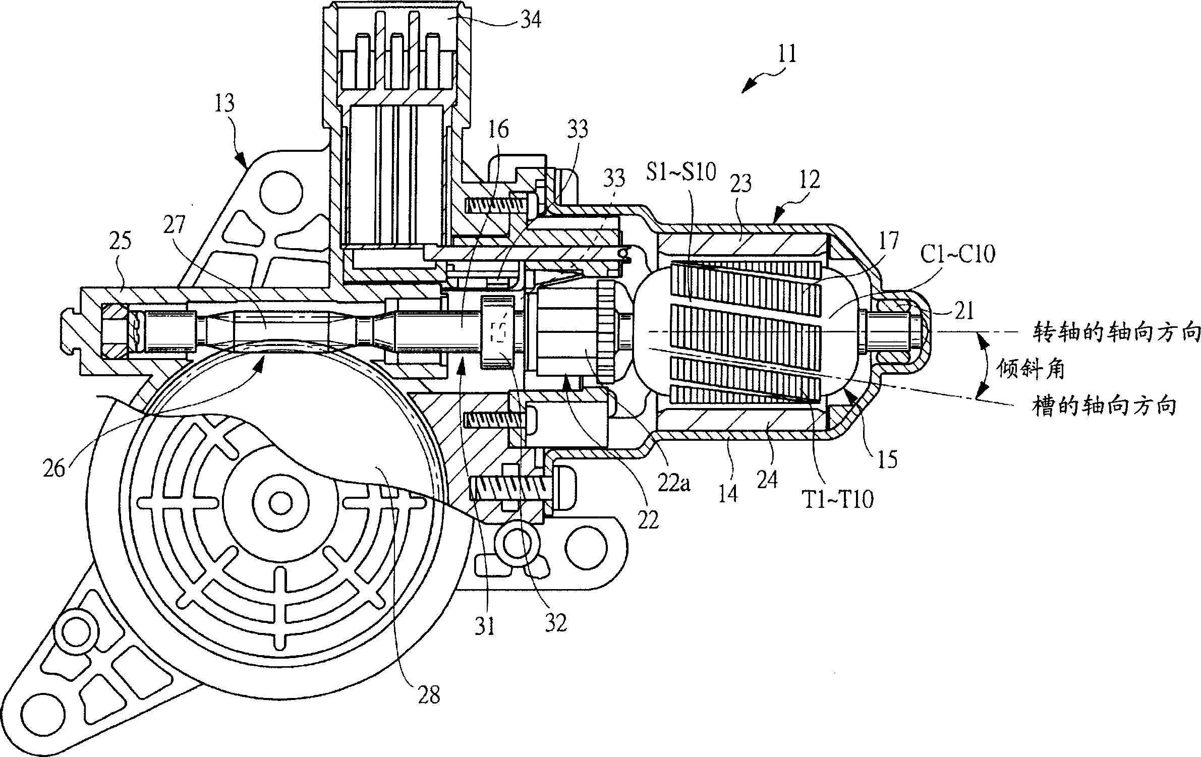
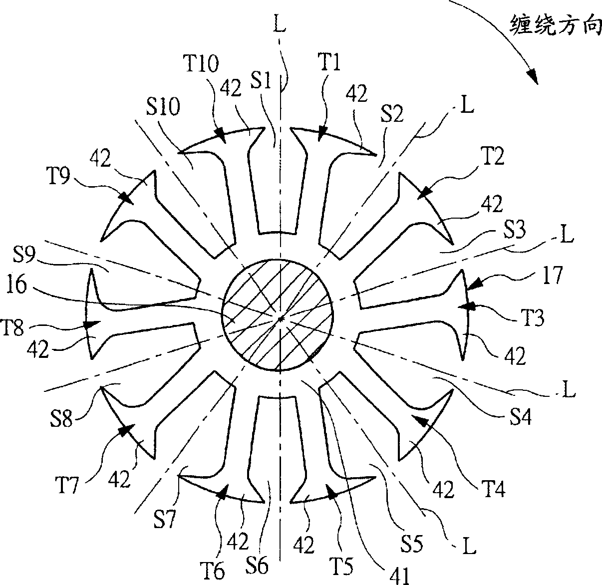
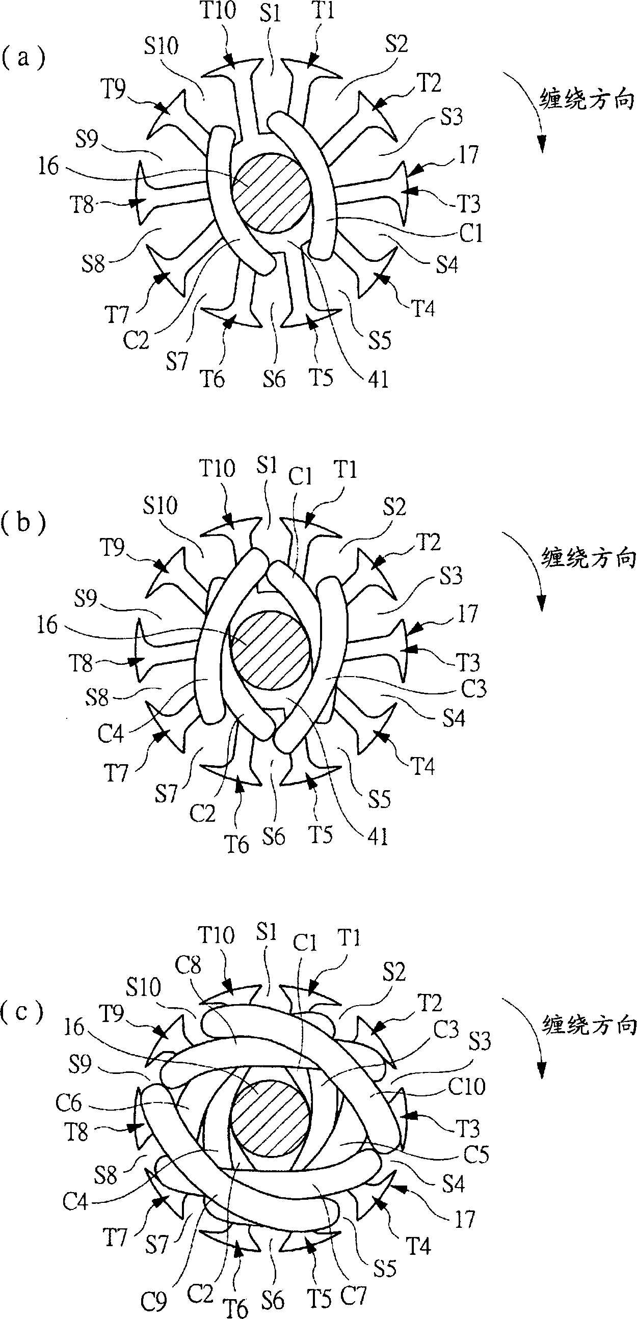
[0025] figure 1 is a partial cross-sectional view of a regulator motor with a motor according to one embodiment of the present invention. figure 2 is to show figure 1 Axial sectional view of the armature core shown. image 3 A-3C shows, respectively, cross-sectional views of a scheme of winding a coil around an armature core.

[0026] like figure 1 As shown, the regulator motor 11 is mounted on a door of a vehicle (not shown) for opening / closing a switchable door glass provided on the door. In this case, the door glass is switchably supported on the door in the vertical direction through the guide member, and is connected to the output shaft (not shown) of the adjuster motor 11 through the adjuster. When the regulator motor 11 works, the rotational movement of the output shaft is converted into the vertical movement of the door glass thro...


PUM


Abstract

A motor includes an armature rotatably accommodated in a motor housing, and a pair of magnets fixed on the inner surface of the motor housing. The armature has an armature core (17) fixed on a rotating shaft (16) and windings accommodated in ten slots (S1-S10) formed in the armature core (17). These slots (S1-S10) have four different shapes, thereby increasing the fill factor of the individual windings. Since the respective slots ( S1 - S10 ) are inclined in the rotational direction with respect to the axial direction of the rotating shaft ( 16 ), the magnetic imbalance caused by the different-shaped slots ( S1 - S10 ) can be made uniform.

Description

technical field [0001] The present invention relates to a motor that converts electrical energy into mechanical energy through magnetic energy, in particular, the present invention relates to a motor equipped with an armature iron core, and coils are wound around the armature iron core in the form of stacked windings. Background technique [0002] The motor has an armature rotatably housed within a motor housing, and a pair of magnets fixed to the inner surface of the motor housing in a manner facing the armature, the motor converts direct current (ie, electrical energy supplied to the armature) ) is converted into rotation of the armature (ie, magnetic energy) for output. [0003] An armature used in such a motor has a rotating shaft and an armature core fixed to the rotating shaft, and is rotatably supported at the rotating shaft in a motor housing. The armature core has a hub portion fixed to the rotating shaft, and a plurality of teeth radially protruding from the hub p...

Claims


Application Information

Patent Timeline
Patent Type & Authority Applications(China)
IPC IPC(8): H02K1/26H02K7/116
Inventor 米田茂广川岛义亲
Owner MITSUBA CORP
Why Eureka
Try Eureka