
Automatic stacking device and production method for stator-rotor iron cores

A production method and stator-rotor technology, applied in the field of automatic stacking device for stator-rotor iron cores, can solve the problems of low stacking coefficient of stator-rotor iron cores, easy damage to the inter-chip insulation layer, and affect the performance of the motor, so as to achieve machine automation Production, eliminating the need for stamping and riveting points, and the effect of high gluing force

Active Publication Date: 2018-10-30
CHONGQING CHANGAN CLUTCH MFG
View PDF3 Cites 2 Cited by
  • Summary
  • Abstract
  • Description
  • Claims
  • Application Information

AI Technical Summary

Problems solved by technology

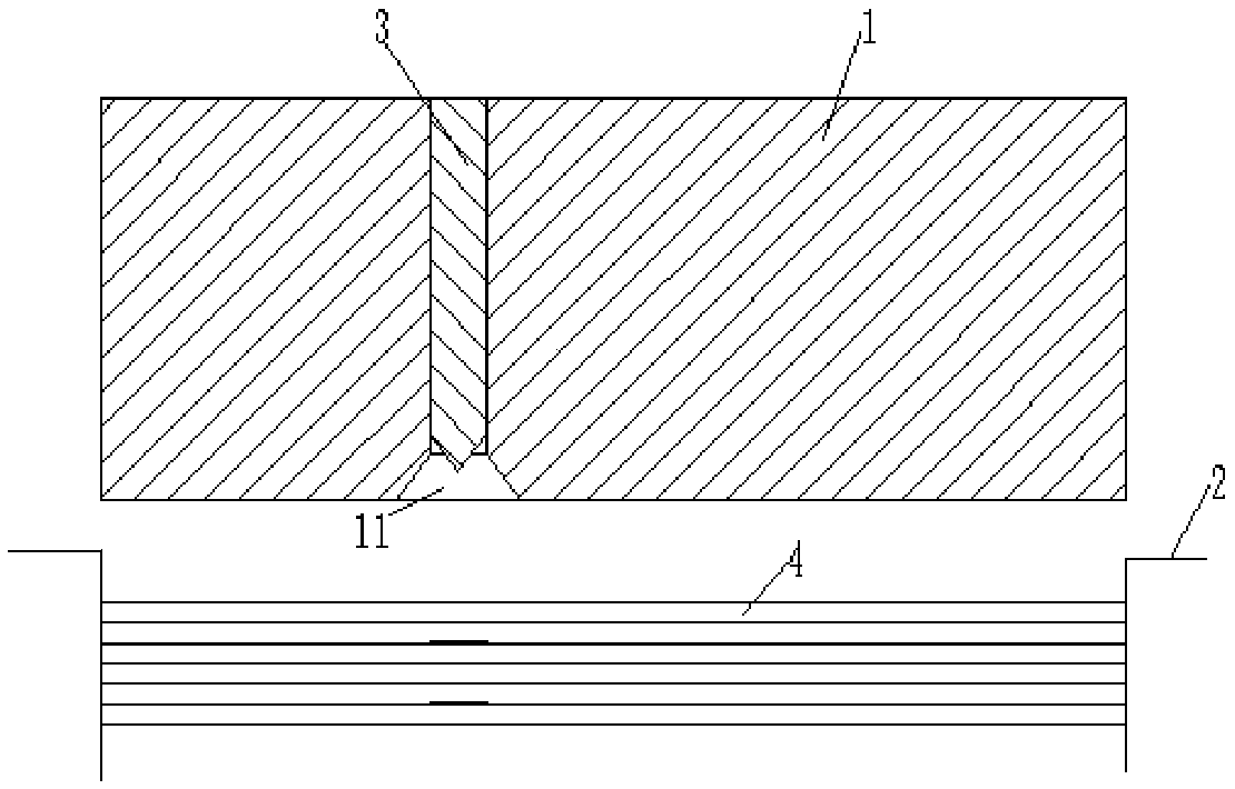
[0004] The purpose of the present invention is to provide an automatic stacking device and production method for stator and rotor cores, so as to alleviate the problem of low stacking coefficient, small stacking force and easy damage to the inter-sheet insulation layer of the stator and rotor cores formed by riveting in the prior art. Technical issues that affect motor performance

Method used


Image

  • Automatic stacking device and production method for stator-rotor iron cores
  • Automatic stacking device and production method for stator-rotor iron cores
  • Automatic stacking device and production method for stator-rotor iron cores

Examples


Embodiment Construction

[0029] The technical solutions of the present invention will be clearly and completely described below in conjunction with the accompanying drawings. Apparently, the described embodiments are some of the embodiments of the present invention, but not all of them. Based on the embodiments of the present invention, all other embodiments obtained by persons of ordinary skill in the art without making creative efforts belong to the protection scope of the present invention.

[0030] In the description of the present invention, it should be noted that the terms "center", "upper", "lower", "left", "right", "vertical", "horizontal", "inner", "outer" etc. The indicated orientation or positional relationship is based on the orientation or positional relationship shown in the drawings, and is only for the convenience of describing the present invention and simplifying the description, rather than indicating or implying that the referred device or element must have a specific orientation, ...


PUM


Abstract

The invention provides an automatic stacking device and production method for stator-rotor iron cores, relating to the technical field of motor stator and rotor punching equipment. The automatic stacking device for the stator-rotor iron cores comprises a blanking male die, a blanking female die and glue spraying nozzles connected with a glue conveying pipe; a plurality of through holes are distributed on the blanking male die, the glue spraying nozzles are respectively inserted and fixed in the through holes, the glue spraying nozzles directly face stator punching sheets / rotor punching sheetspositioned on the blanking female die, the glue spraying nozzles can spray glue liquid on the upper surfaces of the stator punching sheets / the rotor punching sheets before the blanking male die presses the stator punching sheets / the rotor punching sheets positioned on the blanking female die, and the stator punching sheets / the rotor punching sheets can be adhered and fixed with the adjacent statorpunching sheets / the rotor punching sheets through the pressing of the blanking male die. Thereby, the technical problems that the stator-rotor iron cores formed by riveting in the prior art have lowstacking coefficients, low riveting force and easy damages to the insulating layer between the sheets, and the performance of the motor is affected can be alleviated.

Description

technical field [0001] The invention relates to the technical field of stamping equipment for motor stator and rotor, in particular to an automatic stacking device and production method for stator and rotor iron cores. Background technique [0002] The stator and rotor of the motor are the key parts of the motor. They are made of silicon steel sheets with good magnetic conductivity, which are stacked one by one after radial stamping and blanking. The stacking of stator and rotor punching sheets is also a key process in the manufacture of stator and rotor. Most of the manufacturing processes use: ordinary punching press punching, manual weighing, sheet sorting, stator rivet riveting or buckle buckle, rotor rivet riveting or pressing shaft , low work efficiency, low quality. like figure 1 As shown, after the emergence of high-speed punching machines, most of them use the buckle riveting process. It is a fully automatic and efficient production process that realizes in the h...

Claims


Application Information

Patent Timeline
Patent Type & Authority Applications(China)
IPC IPC(8): H02K15/02
CPCH02K15/02
Inventor 谢驰韩荣华
Owner CHONGQING CHANGAN CLUTCH MFG
Learn More