Installing method of portal crane

A technology of a gantry crane and an installation method, which is applied to the cranes, trolleys, transportation and packaging, etc., can solve the problems of difficult adjustment of rigid legs, safety, etc., and achieves accurate cable wind force, reduced cable wind adjustment, and convenient adjustment. Effect

Inactive Publication Date: 2006-09-20
TONGJI UNIV
View PDF0 Cites 24 Cited by
  • Summary
  • Abstract
  • Description
  • Claims
  • Application Information

AI Technical Summary

Problems solved by technology

The general method is to erect the entire rigid leg first, and then lift the girder into place. This method is difficult to adjust the center of gravity of

Method used


Image

  • Installing method of portal crane
  • Installing method of portal crane
  • Installing method of portal crane

Examples


Example Embodiment

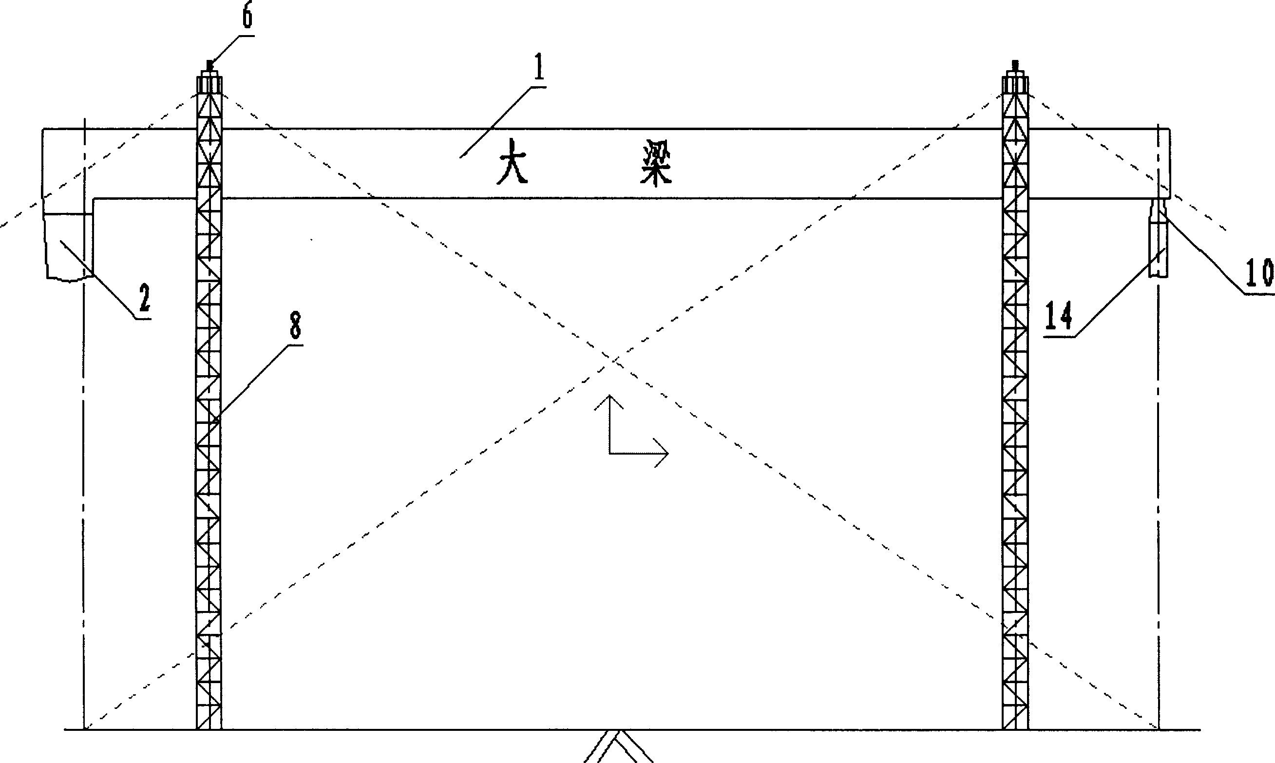
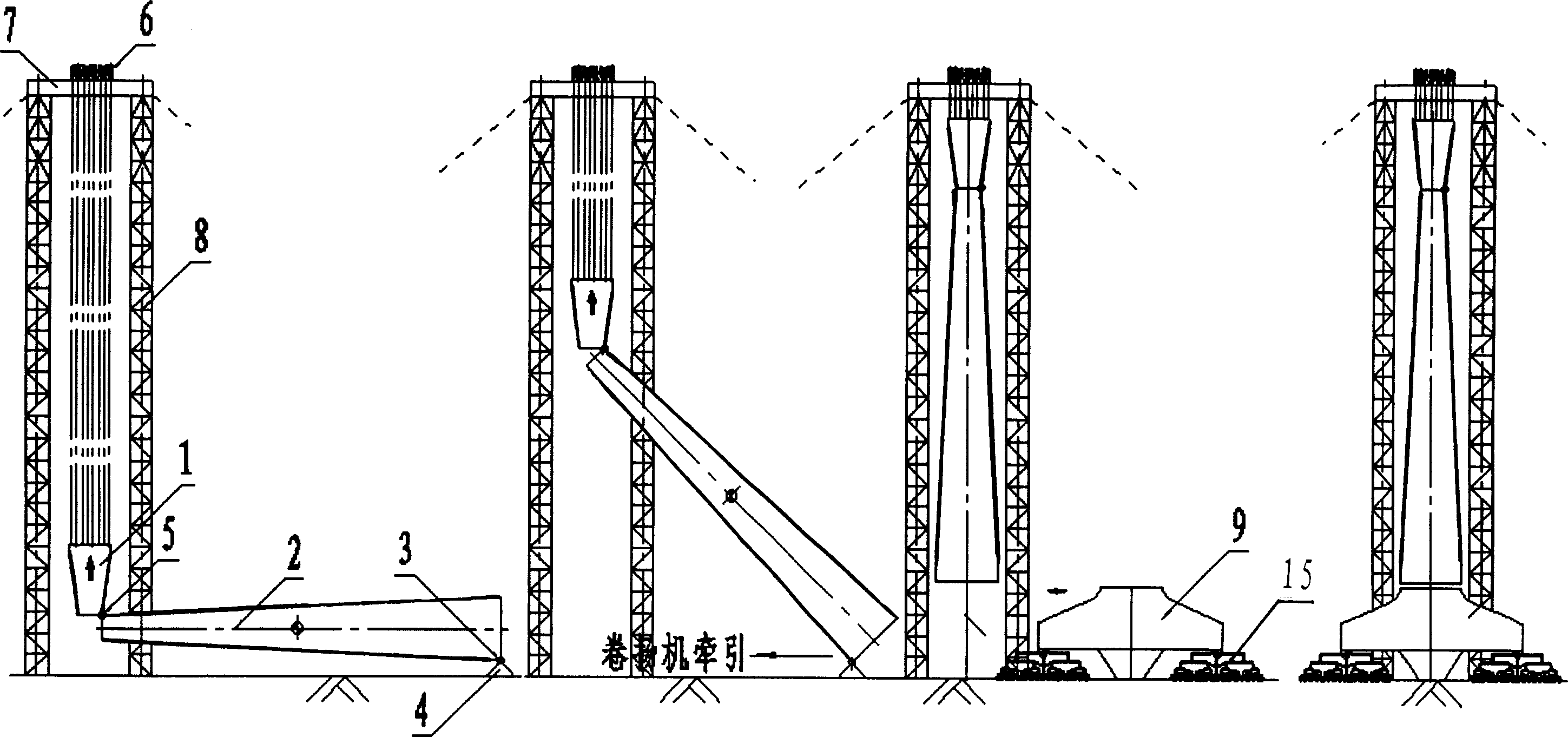
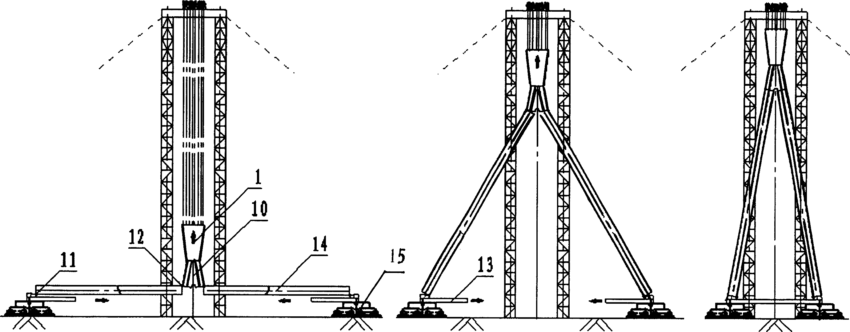
[0009] The present invention will be further described with reference to the accompanying drawings. See figure 1 , 2 3, the present invention consists of beam 1, rigid leg 2, hinge point JX 3, sliding block 4, hinge point JS 5, lifting cylinder 6, tower top gantry beam 7, tower frame 8, walking mechanism 9, A-shaped head 10. Hinge point JB 11, hinge point JA 12, flexible leg lower crossbeam 13, flexible leg 14 and sliding trolley 15.

[0010] installation method:

[0011] 1. Installation of the tower and the gantry beam on the top of the tower

[0012] The present invention uses two pairs of towers 8 as lifting towers. The effective height of the towers 8 varies according to the specific gantry crane. Generally, it can be as high as more than 100 meters, with a cross-section of 4 meters, and a steel pipe lattice structure. The bottom of the frame 8 is connected with the ground foundation by bolts. The gantry beam 7 at the top of the tower is a box-shaped structure. The load capac...


PUM


Abstract

A method for installing the gantry crane features that in the procedure of lifting up the large steel beam, the rigid legs and flexible legs are also lifting. It includes such steps as in-situ assembling master steel beam, hanging the carrier and maintenance hoist from the master beam, standing up two lifting towers, hydraulic lifting while segmenting assembling rigid legs and flexible legs, installing the running mechanism to the legs, and structural installation.

Description

technical field [0001] The invention relates to a method for installing a gantry crane. Background technique [0002] Gantry cranes are mainly used in the shipbuilding industry, and they are currently installed in various ways. The general method is to erect the entire rigid leg first, and then lift the girder into place. This method is difficult to adjust the center of gravity of the rigid leg when the girder is installed, so the safety is poor. In the past, a major engineering accident occurred in a certain factory. big relationship. Contents of the invention [0003] The purpose of the present invention is to provide a new installation method to improve the safety, quickness and reliability of the installation process of the gantry crane. [0004] In order to achieve the above-mentioned purpose, the present invention uses two pairs of "door"-shaped towers as lifting towers, the steel structure girders are assembled on the ground, and the rigid legs are segmented and t...

Claims


Application Information

Patent Timeline
IPC IPC(8): B66C19/00
Inventor 卞永明周贤周秦利升
Owner TONGJI UNIV
Why Eureka
Try Eureka