
Energy-saving force-amplifying transmission device

A transmission device and power boosting technology, applied in the direction of transmission device, gear transmission device, belt/chain/gear, etc., can solve the problem of not being able to increase power, and achieve the effect of reducing power and increasing torque

Inactive Publication Date: 2006-09-27
郭凤明
View PDF0 Cites 6 Cited by
  • Summary
  • Abstract
  • Description
  • Claims
  • Application Information

AI Technical Summary

Problems solved by technology

Its disadvantage is that through the arrangement of the gears, the speed can only be changed, but the power cannot be increased to save energy.

Method used


Image

  • Energy-saving force-amplifying transmission device
  • Energy-saving force-amplifying transmission device
  • Energy-saving force-amplifying transmission device

Examples


Embodiment Construction

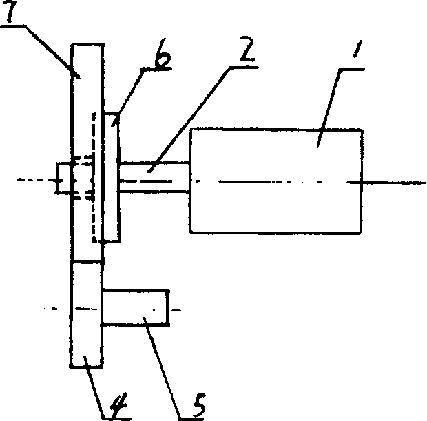
[0012] see figure 1 , The energy-saving booster transmission device includes a motor 1, and a speed-up driving gear is arranged on the motor output shaft 2, and the speed-up driving gear meshes with a driven gear 4, and the driven gear 4 is installed on the power output shaft 5. Output shaft 5 can connect arbitrary power mechanism.

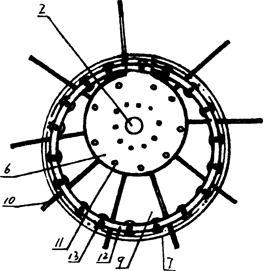
[0013] see figure 1 , 2 , the speed-increasing driving gear includes a disc 6 fixedly sleeved on the motor output shaft 2 and a gear flywheel 7 mounted eccentrically on the motor output shaft 2 against the outer side of the disc 6 .

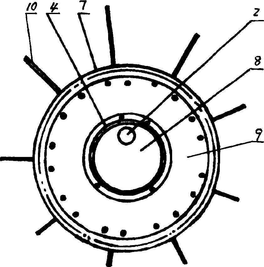
[0014] see image 3 , gear flywheel 7 is made up of flywheel inner ring 8 and the outer ring 9 that has gear teeth at the outer circle end. The outer ring 9 can freely rotate around the inner ring 8 of the flywheel. Flywheel inner ring 8 is fixedly connected with frame.

[0015] see figure 2 , The disc 6 is provided with a plurality of radially protruding movable driving rods 10 along the circumference, and t...


PUM


Abstract

The invention relates to an energy-saving power increase transmission device, which comprises a motor, a speed increase driving gear on the motor output axle, and a driven gear mounted on the power output axle, while said driving and driven gears are meshed. Said speed increase driving gear comprises a disc mounted on the motor output axle and a gear flywheel eccentrically sheathing the motor output axle; wherein the gear flywheel is formed by the inner ring and the outer ring whose end has gear tooth; the disc along the circumference has several radial projected movable dial rods while the outer end of each dial rod is connected to the outer ring of gear flywheel. The invention uses the eccentric and lever theories, to increase the large torque in the same speed of motor. The invention can reduce the power of motor but outputting same torque.

Description

technical field [0001] The invention relates to a gear transmission device, namely an energy-saving booster transmission device. Background technique [0002] In the prior art, the gear transmission device includes a motor, a driving gear on the output shaft of the motor, and a driven gear meshed with the driving gear, and the driven gear is installed on the power output shaft. Its disadvantage is that through the arrangement of the gears, the speed can only be changed, but the power cannot be increased to save energy. Contents of the invention [0003] The object of the present invention is to provide an energy-saving booster transmission device that increases power output or saves energy by changing the gear structure to address the above-mentioned shortcomings. [0004] The technical solution of the present invention is: the energy-saving power-increasing transmission device includes a motor, and there is a speed-up driving gear on the output shaft of the motor. The sp...

Claims


Application Information

Patent Timeline
Patent Type & Authority Applications(China)
IPC IPC(8): F16H1/04
Inventor 郭凤明
Owner 郭凤明
Learn More