
Mold structure

A mold and mold base technology, applied in the field of mold structure that can reduce the coaxiality error, can solve the problems of inconvenient mold manufacturing and assembly, cumbersome methods, not on the same straight line, etc., and achieve the effect of reducing the coaxiality error

Inactive Publication Date: 2006-10-04
HONG FU JIN PRECISION IND (SHENZHEN) CO LTD +1
View PDF0 Cites 4 Cited by
  • Summary
  • Abstract
  • Description
  • Claims
  • Application Information

AI Technical Summary

Problems solved by technology

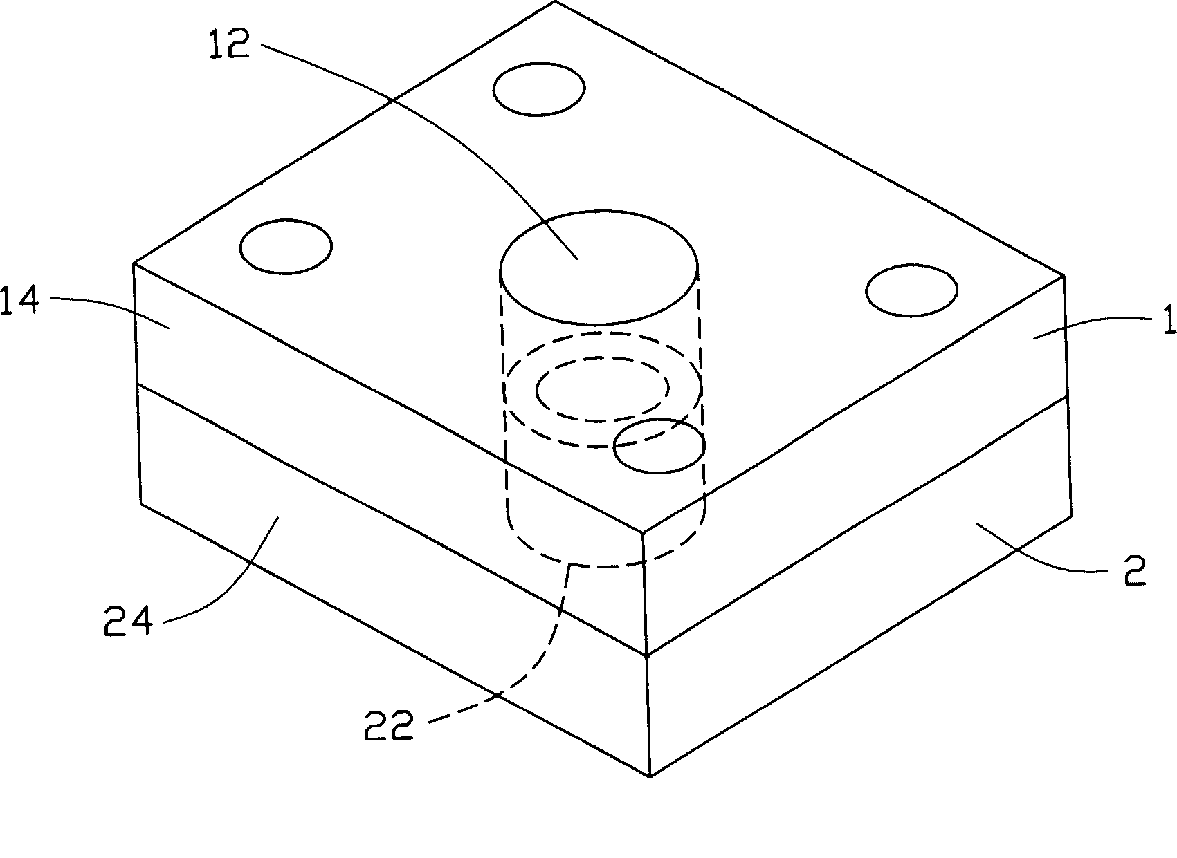
Although this kind of mold can process the desired shape, but due to the large error after the assembly of the upper mold and the lower mold, the optical axes of the upper and lower surfaces of the processed object are not on the same straight line, which cannot meet the high-quality processing requirements.
In order to reduce the error, it is often necessary to dismantle the mold for correction or reassemble to reduce the coaxiality error. This method is cumbersome and reinstallation may not be able to adjust well, which brings great inconvenience to mold manufacturing and assembly.

Method used


Image

  • Mold structure
  • Mold structure

Examples


Embodiment Construction

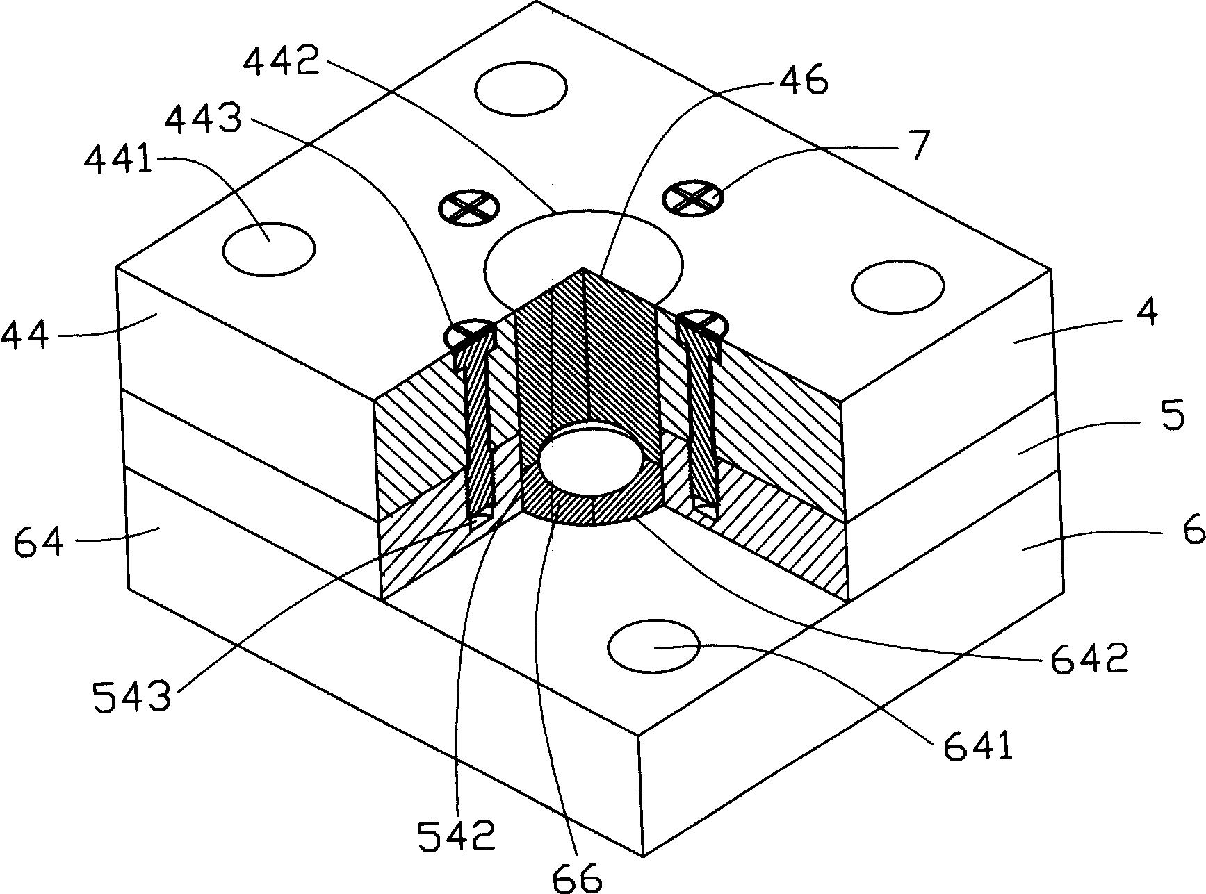
[0011] see figure 2 , The preferred embodiment of the mold structure of the present invention takes the injection molding plastic mold as an example.

[0012] The mold structure includes an upper mold 4, a buffer layer 5, a lower mold 6 and several screws 7.

[0013] Upper mold 4 is divided into two parts, comprises upper mold base 44 and upper mold kernel 46. An opening 442 is opened in the middle of the upper mold base 44 . The upper die core 46 is columnar, and one end surface matches a surface of the processed object. Four corners of the upper die base 44 are respectively provided with pin holes 441 , and the pin holes 441 pass through the upper die base 44 . On the upper mold base 44 and around the opening 442 , four adjustment holes 443 are provided, and the four adjustment holes 443 pass through the upper mold base 44 and can be matched with the screws 7 .

[0014] The buffer layer 5 is disposed between the upper mold 4 and the lower mold 6 , and the buffer layer 4...


PUM


Abstract

The invention discloses a die construction, which is characterized by the following: one top die which is composed of one upper bolster, one top die seed and one breaker wherein the upper bolster has one open and the surrounding open installs a plurality of adjustment hole; one top die seed is fit for the open of upper bolster; one breaker has a via hole in the middle, the surrounding via hole installs a plurality of adoption hole, the via hole of breaker is alignment to open axial trace of upper bolster; one counterdie which is composed of one die shoe, one counterdie seed and screw, wherein the counterdie installs one open in the middle; one counterdie seed is fit for the open of counterdie; the screw is fit for adjustment hole of upper bolster and adaption hole of breaker.

Description

【Technical field】 [0001] The invention relates to a mold structure, in particular to a mold structure capable of reducing coaxiality errors. 【Background technique】 [0002] With the continuous development of science and technology, portable electronic devices, such as mobile phones, are widely used and tend to be lightweight, beautiful and multi-functional. Among them, the camera function is an additional function of the newly developed portable electronic devices in recent years. Mobile phones with digital cameras are more and more popular among users because they can realize the instant shooting function and are easy to use. Due to the small volume of the mobile phone, the digital camera lens module to be installed in the mobile phone has a small volume. While people are pursuing the miniaturization of digital camera modules for mobile phones, they also hope to have higher imaging quality for the objects they shoot, and the imaging quality of objects depends to a large ex...

Claims


Application Information

Patent Timeline
Patent Type & Authority Applications(China)
IPC IPC(8): B29C33/30B29C45/26C03B11/06
Inventor 林志泉
Owner HONG FU JIN PRECISION IND (SHENZHEN) CO LTD
Learn More