Spray and whirl type aerobic fermentation tank

An aerobic fermentation, spray-rotating technology, applied in the direction of bioreactor/fermenter combination, specific-purpose bioreactor/fermenter, biochemical instruments, etc. The bottom erosion is serious and the service life of the tank is short, so as to facilitate the maintenance and operation of the equipment, improve the capacity and mass transfer coefficient and unit output, and reduce the mechanical stirring load.

Inactive Publication Date: 2006-10-04
浙江省天正设计工程有限公司
View PDF0 Cites 7 Cited by
  • Summary
  • Abstract
  • Description
  • Claims
  • Application Information

AI Technical Summary

Problems solved by technology

[0002] At present, the equipment used in aerobic fermentation production is a general-purpose fermenter. Its structural feature is that a multi-stage high-power stirring device is installed in the tank. There are three ventilation methods. One is to set a single-hole tube at the bottom of the tank. The air holes of the hole tube are opened downwards to achieve the effect of eliminating the solid matter at the bottom of the tank while distributing air, but this will cause serious erosion of the bottom of the tank and a short service life of the tank; the second is to use a porous ring There are many circles of small holes at the bottom of the annular tube, and the air distribution is more uniform during use, but the material is easy to block the pores, resulting in incomplete sterilization; the third is to set 4-6 L-shaped branch pipes in the annular pipe, and the air outlets of the branch pipes are uniform. Facing the center line of the fermenter, its structure is simple, but there is a problem that it cannot completely eliminate the solid matter at the bottom of the tank; people have found in actual use that the general-purpose fermenter aeration device also has a direct proportional relationship between the diameter of the bubble and the amount of ventilation and direct steam flow. Disadvantages of violent vibration of the tank during actual consumption

Method used


Image

  • Spray and whirl type aerobic fermentation tank
  • Spray and whirl type aerobic fermentation tank
  • Spray and whirl type aerobic fermentation tank

Examples


Embodiment Construction

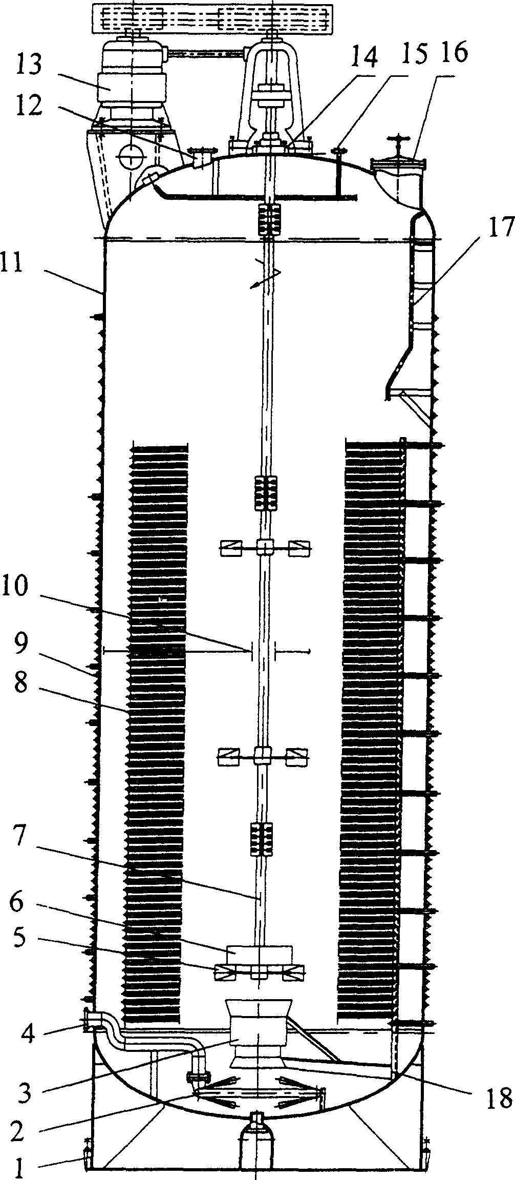
[0010] exist figure 1 Among them, the present invention includes a housing 11, a base 1, a mechanical stirrer 5 and a fixed frame 18, the housing 11 is fixedly connected to the base 1, and the housing 11 is provided with a manhole 16, an air inlet 4 and The air outlet 12, the housing 11 is fixedly connected with the inner coil 8, the housing 11 is provided with a transmission device 13, and the housing 11 is provided with a rotating shaft 7, and the transmission device 13 is matched with the rotating shaft 7 , a mechanical stirrer 5 is installed on the rotating shaft 7, and the rotating shaft 7 and the mechanical stirrer 5 are located in the space surrounded by the inner coil tube 8, and the ejector 3 is installed under the mechanical stirrer 5, and the ejector The bottom of 3 is provided with jet mixing and stirring device 2, which is connected with air inlet 4; A special-shaped pipe 9 is fixedly arranged, and the special-shaped pipe 9 is spirally coiled around the casing 11...


PUM


Abstract

The related rotary aerobic fermentor comprises a shell fixed on a base that contains hole for people and gas inlet/outlet, an inner coil pile and rotary shaft inside matched with gear; a mechanical stirrer on the shaft and both in the space formed by coil pipe, and a fixing frame. Wherein, it arranges a spraying mixer under an injector below the stirrer. This invention is simple, needs low energy consumption, and can improve fermentation performance.

Description

technical field [0001] The invention belongs to fermentation production equipment, in particular to a spray-rotating aerobic fermentation tank. Background technique [0002] At present, the equipment used in aerobic fermentation production is a general-purpose fermenter. Its structural feature is that a multi-stage high-power stirring device is installed in the tank. There are three ventilation methods. One is to set a single-hole tube at the bottom of the tank. The air holes of the hole tube are opened downwards to achieve the effect of eliminating the solid matter at the bottom of the tank while distributing air, but this will cause serious erosion of the bottom of the tank and a short service life of the tank; the second is to use a porous ring There are many circles of small holes at the bottom of the annular tube, and the air distribution is more uniform during use, but the material is easy to block the pores, resulting in incomplete sterilization; the third is to set 4...

Claims


Application Information

Patent Timeline
Patent Type & Authority Applications(China)
IPC IPC(8): C12M1/02
CPCC12M27/02C12M29/06C12M27/24
Inventor 薛才利何德员陈宝锋
Owner 浙江省天正设计工程有限公司
Why Eureka
Try Eureka