Adjustable frequency-stabilizing voltage-stabilizing variable-frequency variable-voltage power supply

A technology of frequency stability and power supply, applied in the field of adjustable power supply, can solve problems such as easy generation of high voltage, large power supply, complex control circuit, etc., to achieve safe switching devices, good frequency and voltage conversion characteristics, and simple control circuit Effect

Inactive Publication Date: 2006-10-11
章祖文
View PDF0 Cites 8 Cited by
  • Summary
  • Abstract
  • Description
  • Claims
  • Application Information

AI Technical Summary

Problems solved by technology

The method of circuit operation is to use the diagonal bridge arms as a group, switch two groups of IGBTs in reverse phase, and generate alternating current in the bridge CL series circuit, and then transmit the variable frequency power to the load through the transformer with L as the primary coil. The characteristic is that alternating current is generated in a single CL series circuit, the control circuit is more complicated, high voltage is easy to be generated on the IGBT, and the power supply cannot be made very large
[0003] The utility model patent "Portable DC Stabilized Voltage Steady Current Variable Voltage Power Supply" (patent number: ZL032640056) disclosed by the applicant discloses a new inverting switching power supply, which uses two IGBTs to switch two coils in inverting phase. Alternating currents are generated in two coils, which can be wound on two ferrite toroidal cores or on one ferrite toroidal core, and the transformer on the core can turn the The frequency conversion energy is sent out. This kind of power supply control circuit is simple, but it is also easy to generate high voltage on the IGBT.

Method used


Image

  • Adjustable frequency-stabilizing voltage-stabilizing variable-frequency variable-voltage power supply
  • Adjustable frequency-stabilizing voltage-stabilizing variable-frequency variable-voltage power supply
  • Adjustable frequency-stabilizing voltage-stabilizing variable-frequency variable-voltage power supply

Examples


Embodiment 1

[0015] Embodiment 1: Single-phase adjustable frequency-stabilized voltage-stabilized variable-frequency variable-voltage power supply (taking phase A as an example)

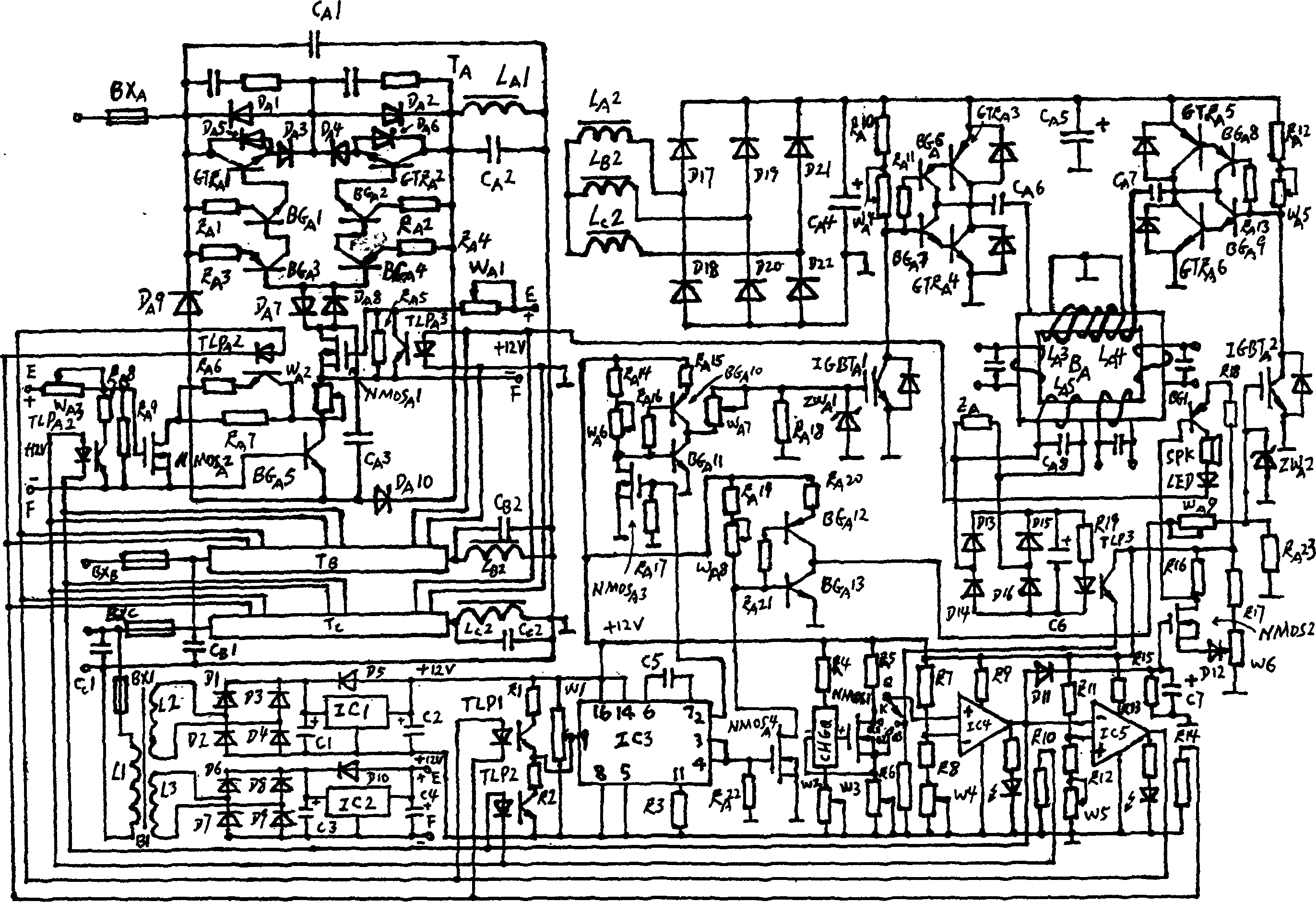
[0016] The present invention consists of a triode voltage regulating circuit T A , A reverse-phase switching signal amplifier circuit (FXKGXHFDDL), A reverse-phase switching power supply circuit (FXKGDYDL), A-phase transformer load circuit, load voltage sampling circuit (FZQYDL), load environment change voltage sampling circuit (HJQYDL), sampling signal amplification circuit (QYXHFDDL), sampling signal control circuit (QYXHKZDL), power supply protection start control signal generation circuit, A-phase transformer rectification filter circuit (ZLLBDL), inversion switch signal generation circuit, auxiliary power supply circuit (FZDYDL) and independent power supply circuit (DLDYDL) composition.

[0017] Triode voltage regulator circuit T A By fuse BX A , Transistor GTR A 1. GTR A 2. BG A 1--BG A 5. Field effe...

Embodiment 2

[0032] Embodiment 2: Single-phase adjustable frequency-stabilized voltage-stabilized variable-frequency variable-voltage power supply (taking phase A as an example)

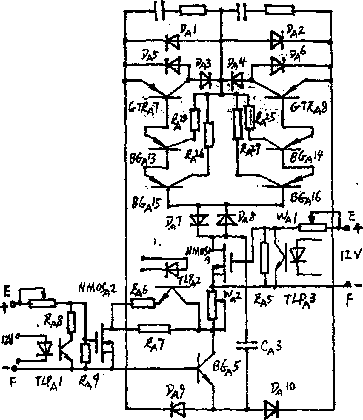
[0033] The circuit of embodiment 2 is the same as the circuit of embodiment 1, the difference is: the triode voltage regulating circuit T A Use the first alternative circuit for substitution (see figure 2 ).

[0034] Triode voltage regulator circuit T A By fuse BX A , Transistor GTR A 7. GTR A 8. BG A 13--BG A 16. Field effect transistor NMOS A 1. NMOS A 2. Diode D A 1-D A 10. Adjustable resistance W A 1--W A 3. Resistance R A 5-R A 9. R A 24-R A 27. Capacitance C A 1--C A 3 and other components, triode GTR A 7 emitters with fuse BX A Connect to one end of the mains 380V in series, and connect the collector to the diode D A 3 anode and diode D A 5 anode common, diode D A 3's cathode connected to diode D A 1 anode, diode D A 2 anode and diode D A 4 common terminal of cathode, diode D A ...

Embodiment 3

[0035] Embodiment 3: Single-phase adjustable frequency-stabilized voltage-stabilized variable-frequency variable-voltage power supply (taking phase A as an example)

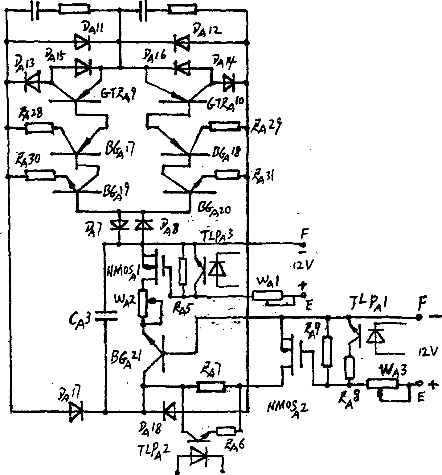
[0036] The circuit of embodiment 3 is the same as the circuit of embodiment 1, the difference is: the triode voltage regulating circuit T A Use the second alternative circuit for substitution (see image 3 ).

[0037] Triode voltage regulator circuit T A By fuse BX A , Transistor GTR A 9. GTR A 10. BG A 17--BG A 21. Field effect transistor NMOS A 1. NMOS A 2. Diode D A 7.D A 8.DA 11--D A 18. Adjustable resistance W A 1--W A 3. Resistance R A 5-R A 9. R A 28-R A 31. Capacitance C A 1--C A 3 and other components, diode D A 11 anode and diode D A 13 The common terminal of the cathode and the fuse BX A One end of the mains 380V is connected in series, the diode D A 13 Anode and Diode D A 15 anode common termination triode GTR A collector of 9, diode D A The cathode of 11 is connected to the ...


PUM


Abstract

The disclosed tunable stable-frequency/voltage frequency/voltage-changing power comprises: a three-phase transformer rectification filter circuit, a reversing-switch signal generation/ amplification circuit, an auxiliary power circuit, an independent power circuit, a triode voltage-regulation circuit, a reversing-switch power circuit, a transformer load circuit, a load voltage sampling circuit, a load environmental change voltage sampling circuit, a sample signal amplification/control circuit, and a initiation-control signal generation circuit for power protection. This product has well performance.

Description

technical field [0001] The invention relates to an adjustable power supply, in particular to an adjustable frequency-stabilized voltage-stabilized variable-frequency variable-voltage power supply. Background technique [0002] At present, the single-phase variable frequency power supply usually adopts a bridge circuit, four IGBTs are used as bridge arms, and the bridge itself is a CL series circuit. The method of circuit operation is to use the diagonal bridge arms as a group, switch two groups of IGBTs in reverse phase, and generate alternating current in the bridge CL series circuit, and then transmit the variable frequency power to the load through the transformer with L as the primary coil. The characteristic is that alternating current is generated in a single CL series circuit, the control circuit is more complicated, high voltage is easy to be generated on the IGBT, and the power supply cannot be made very large. [0003] The utility model patent "Portable DC Stabili...

Claims


Application Information

Patent Timeline
Patent Type & Authority Applications(China)
IPC IPC(8): H02M5/44H02M5/458G05F1/12G05F1/44
Inventor 章祖文
Owner 章祖文
Why Eureka
Try Eureka