Substrate recognition method and element assemble mounting system

A technology of installation system and identification method, applied in electrical components, electrical components, etc., can solve problems such as hindering installation processing, increasing installation machine processing burden, shortening production rhythm, etc., to achieve the effect of smooth production

Inactive Publication Date: 2006-10-18
YAMAHA MOTOR CO LTD
View PDF1 Cites 1 Cited by
  • Summary
  • Abstract
  • Description
  • Claims
  • Application Information

AI Technical Summary

Problems solved by technology

[0006] However, in order to efficiently perform component mounting processing in a mounting device composed of many unit mounters, it is necessary to reduce the processing load of the unit mounters to shorten the production tempo, but on the other hand, it is more important to equally distribute each unit Processing burden on the installer
That is, if the unevenness of the processing load makes the processing time of a certain device (process) too long, the production rhythm of the entire mounting device depends on the processing t

Method used


Image

  • Substrate recognition method and element assemble mounting system
  • Substrate recognition method and element assemble mounting system
  • Substrate recognition method and element assemble mounting system

Examples


Embodiment Construction

[0027] Embodiments of the present invention will be described below with reference to the drawings.

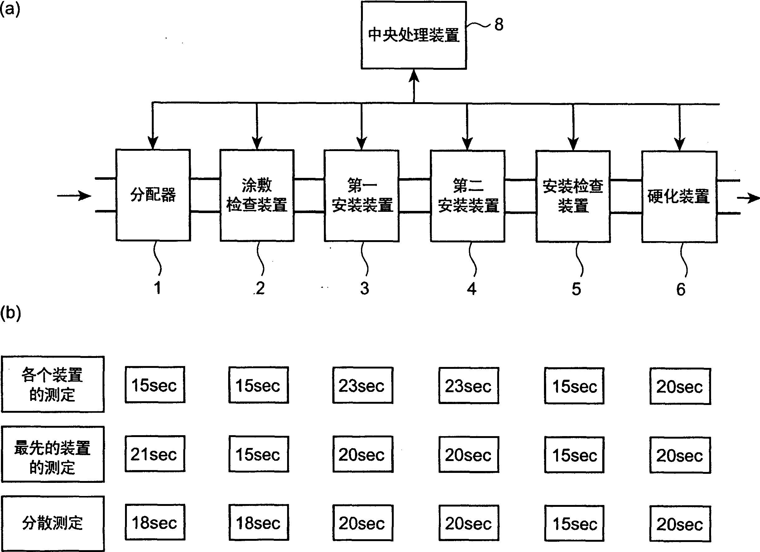
[0028] figure 1 (a) schematically shows a component mounting line related to the component mounting system of the present invention (a component mounting system for substrate identification according to the present invention). In this production line, a dispenser 1, a coating inspection device 2, a first mounting device 3, and a second mounting device 4 are arranged in series between a loader and an unloader (both are not shown in the figure). , Install inspection device 5 and hardening device 6 and constitute. Furthermore, the structure is as follows: While conveying a circuit board (hereinafter referred to simply as a board), solder paste is applied sequentially, components are mounted, solder paste is cured, etc., and the printed inspection device 2 is used to inspect the board subjected to the solder paste coating process. , and use the mounting inspection device 5 to in...


PUM


Abstract

The substrate identification method of the present invention can reasonably perform the substrate identification process of each device included in the component mounting production line, and at the same time can smoothly produce the circuit substrate. For each component mounting line including dispenser (1), coating inspection device (2), first mounting device (3), second mounting device (4), mounting inspection device (5) and hardening device (6) The device compares the production rhythm of each device (1 to 6) and determines the speed of the production rhythm of the production line. When the device is a device that uses a partial mark attached to the substrate, that is, a device that performs image recognition on the mark to generate correction data, the recognition operation of part or all of the mark that needs to be image recognized in the device is assigned to the use The above-mentioned distribution is carried out in one or more devices used in the process preceding the process of the device, and at the same time, the production rhythm of each device is not slower than the production rhythm of the hardening device.

Description

technical field [0001] The present invention relates to a component mounting system in which a plurality of devices such as a solder printing device, a dispenser, a mounting device, a reflow oven, and various inspection devices are arranged in series, and particularly relates to a method capable of rationally performing substrate identification on the component mounting system and device. Background technique [0002] As a conventional mounting device, a plurality of mounting machines (referred to as a unit mounting machine) are arranged in a row, and components are mounted on a circuit board in a distributed manner. [0003] Among such mounting devices, each device performs mounting processing in a state where the circuit board is positioned at a predetermined position by the positioning device. However, at this time, due to the position deviation of the circuit board relative to the main body of the device and the relative position deviation of the printed wiring pattern ...

Claims


Application Information

Patent Timeline
IPC IPC(8): H05K13/04
Inventor 太田裕之
Owner YAMAHA MOTOR CO LTD
Why Eureka
Try Eureka