
Cast-in-place concrete hollow plate

A cast-in-situ concrete and hollow slab technology is applied in the field of cast-in-place concrete hollow slabs, which can solve the problems of low ability to bear concentrated loads, low force-bearing and force-transmitting capacity of cast-in-situ concrete hollow slabs, etc.

Inactive Publication Date: 2006-10-25
湖南邱则有专利战略策划有限公司
View PDF3 Cites 0 Cited by
  • Summary
  • Abstract
  • Description
  • Claims
  • Application Information

AI Technical Summary

Problems solved by technology

However, the ability of this formwork member to participate in the force bearing and transmission of the cast-in-place concrete hollow slab is low, especially the ability to bear the concentrated load is low

Method used


Image

  • Cast-in-place concrete hollow plate
  • Cast-in-place concrete hollow plate
  • Cast-in-place concrete hollow plate

Examples


Embodiment Construction

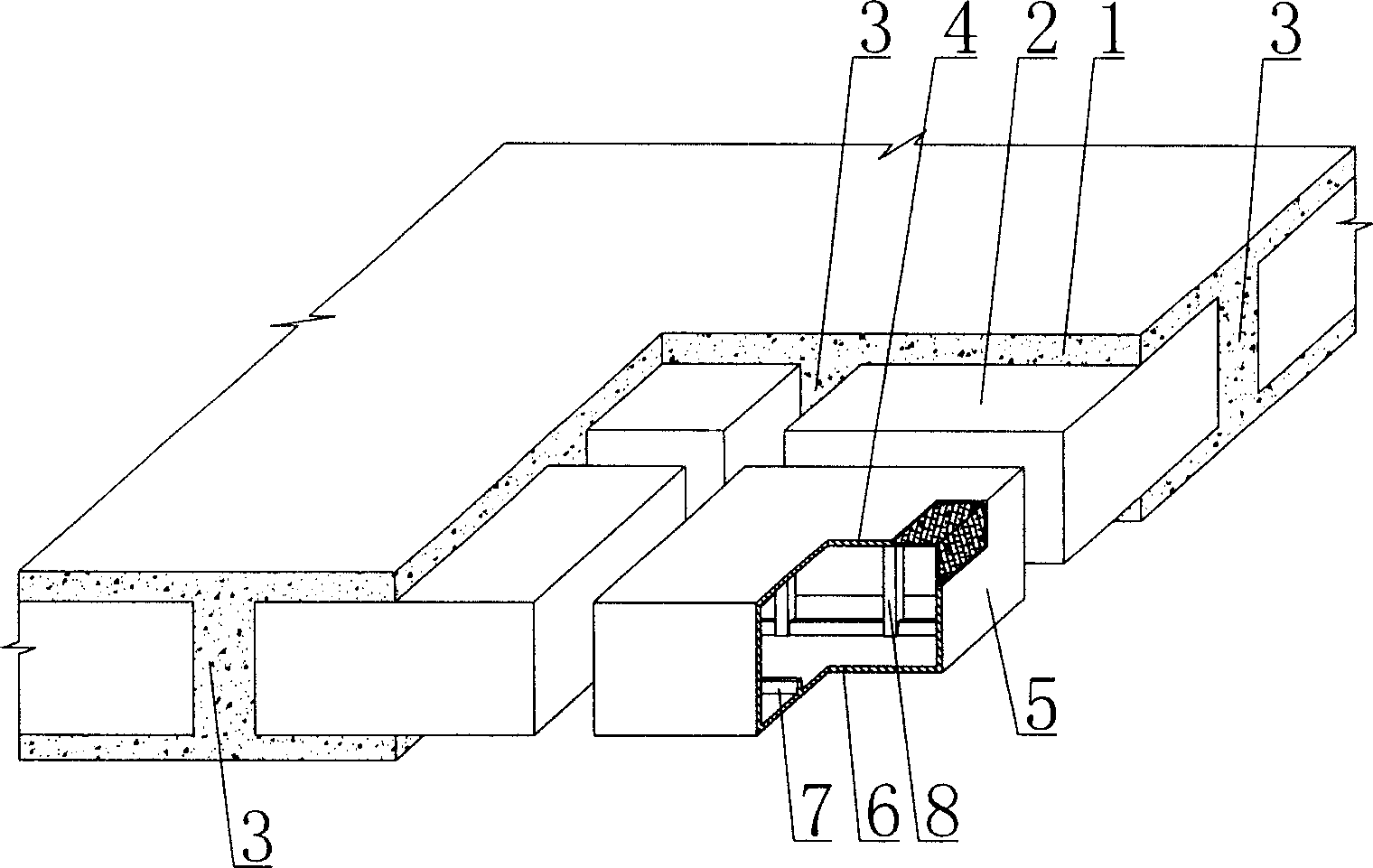
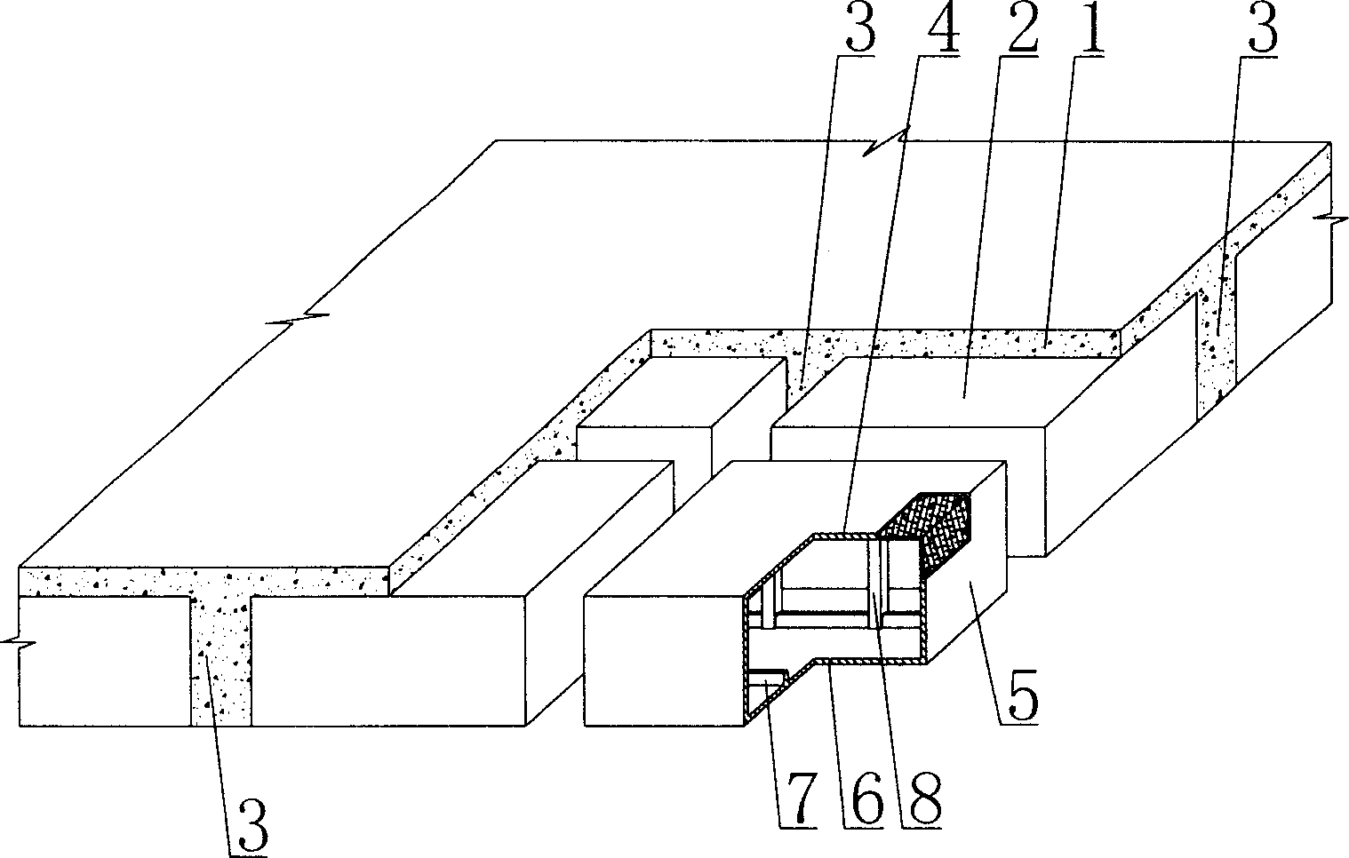
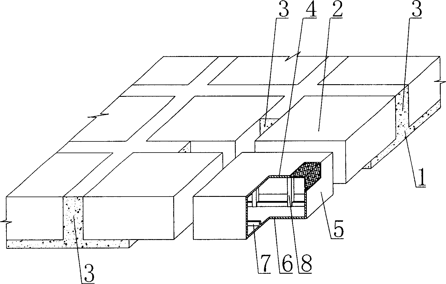
[0078] The present invention will be further described below in conjunction with the accompanying drawings and embodiments.

[0079] As shown in the accompanying drawings, the present invention includes reinforced concrete 1, formwork components 2, the formwork components 2 are wrapped in the reinforced concrete 1, the formwork components 2 are arranged alternately, and there are cast-in-situ reinforced concrete ribs 3 between each other, and the formwork The component 2 includes an upper plate 4, surrounding side walls 5, and a lower base plate 6, and the upper plate 4, the surrounding side walls 5, and the lower base plate 6 form a closed cavity formwork member 2, and the upper plate 4, the surrounding side walls 5, and the lower base plate 6 At least one of them is provided with a reinforcing rib 7, which is characterized in that there is at least one rod 8 in the closed cavity of the formwork member 2, and at least one end of the rod 8 intersects with at least one reinforci...


PUM


Abstract

The invention is a cast-in-site concrete hollow slab, comprising reinforced concrete and form components, where the form components are wrapped in the reinforced concrete, and spacedly arranged, cast-in-site reinforced concrete ribs are arranged between them and each form component comprises top plate, peripheral side wall and infrabasal plate, which compose a closed cavity form component, at least one of the top plate, peripheral side wall and infrabasal plate is provided with reinforcing ribs and it is characterized in that the closed cavity of the form component is provided with at least a rod, at lest one end of the rod intersects and connects with at least a reinforcing rib. And the invention is applied to cast-in-site reinforced concrete or prestressed reinforced concrete hollow floor systems, house covers, walls, foundation slabs and hollow bridges.

Description

(1) Technical field [0001] The invention relates to a cast-in-place concrete hollow slab. (2) Background technology [0002] At present, the cast-in-place concrete hollow slab is a widely used floor structure, and the lightweight permanent tire mold filled in it includes hollow tubes and cavity formwork components. For example, the patent No. ZL99249798.1, which the applicant applied for on November 29, 1999, is a utility model patent named "fiber-reinforced thin-walled member for reinforced concrete filling", which discloses a thin-walled formwork member, including an upper plate, The surrounding side walls, the lower bottom plate, the upper plate, the surrounding side walls and the lower bottom plate form a polyhedron cavity. Another example is that the application number applied by the applicant on November 23, 2001 is 01140106.0, the publication number is CN1356442, and the name is called "a kind of cavity structure formwork for cast-in-place reinforced concrete floor s...

Claims


Application Information

Patent Timeline
IPC IPC(8): E04B1/16E04B5/36E04C5/00E04G15/06
Inventor 邱则有
Owner 湖南邱则有专利战略策划有限公司
Features
  • Generate Ideas
  • Intellectual Property
  • Life Sciences
  • Materials
  • Tech Scout
  • Unparalleled Data Quality
  • Higher Quality Content
  • 60% Fewer Hallucinations
Learn More