Light channel device

A technology of optical channels and pipes, applied in projection devices, optics, optical components, etc., can solve problems such as unsolvable shortcomings, glass breakage/displacement, glass deformation, etc., to increase stability and efficiency, and reduce displacement. /deformation/fracture effect

Inactive Publication Date: 2006-10-25
DELTA ELECTRONICS INC
View PDF0 Cites 4 Cited by
  • Summary
  • Abstract
  • Description
  • Claims
  • Application Information

AI Technical Summary

Problems solved by technology

[0007] However, the above-mentioned structure only uses glue as the only fixing mechanism, and cannot bear the pressure. In addition, it is very easy to change due to the glued part at high temperature, resulting in breakage / displacement / deformation of the glass slide, which reduces the stability and performance of use under high temperature. , and the clamp directly holds the slide, which is more likely to cause damage to the slide and reduce the use time
[0008] In addition, in the above-mentioned device method, the outer surfaces of the slides are clamped by the clamp, but the deformation / displacement / breakage of the slides is easily caused at high temperature, and if the slides cannot withstand the pressure caused by the clamp Otherwise, deformation or breakage will occur, and glass slides of different sizes and shapes cannot be used in different projection systems.
[0009] In addition, even if the reflectors are combined in different ways, the shortcomings still cannot be solved

Method used


Image

  • Light channel device
  • Light channel device
  • Light channel device

Examples


Embodiment Construction

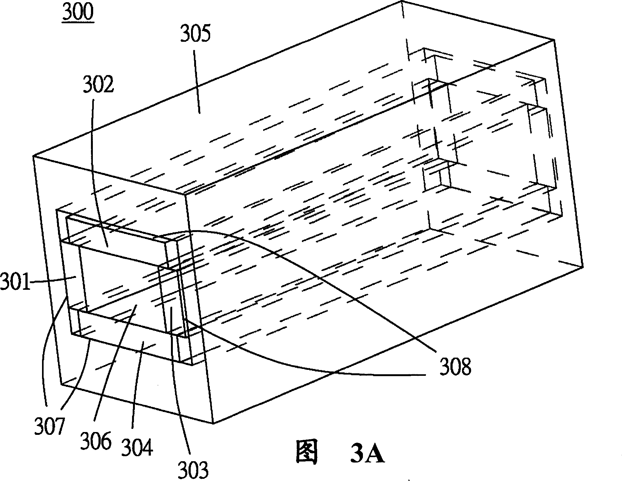
[0033] Figure 3A, Figure 3B A schematic diagram of a first embodiment of the optical channel device 300 of the present invention is shown, wherein FIG. 3A is a perspective view of the first embodiment of the optical channel device 300 of the present invention, Figure 3B is a cross-sectional view of FIG. 3A. Please refer to Figure 3B , the optical channel device 300 is composed of a first reflective sheet 301 , a second reflective sheet 302 , a third reflective sheet 303 , a fourth reflective sheet 304 and a sleeve 305 . Wherein the first reflective sheet 301, the second reflective sheet 302, the third reflective sheet 303 and the fourth reflective sheet 304 are stacked together, and the inner surface surrounded by these reflective sheets forms a rectangular hollow pipe , which is the optical channel 306 . And wherein the first reflector 301, the second reflector 302, the third reflector 303 and the fourth reflector 304 are made of glass, and the inner surface of each of ...


PUM


Abstract

The present invention provides an optical channel device consisting of at least one reflector plate and sleeve, wherein these reflector plates mutually laminated to form one hollow pipe for light passing. Said sleeve covers whole or a part of these reflector plates.

Description

technical field [0001] The present invention relates to a light tunnel module, in particular to a light tunnel module with high stability, no deformation at high temperature, and shareability. Background technique [0002] In a general projection system, a light concentrating system is usually required to uniformly distribute the incident light before exiting. [0003] General projection systems can be divided into image tubes (CRT), liquid crystal projectors (LCD), digital light source devices (DLP) and microdisplays according to different technologies. Please refer to figure 1 , which shows the Chinese Taiwan Publication No. 517855, which is a known digital light source device 10, which has a light source 1, a reflector 2, a color wheel 4, a converging system 3, a lens 5, A digital micromirror device 6 (Digital Micro-mirror Device, DMD) and a lens 7 . The light concentrating system 3 is a hollow pipe, that is, an optical channel, for light to enter and exit. [0004] A...

Claims


Application Information

Patent Timeline
Patent Type & Authority Applications(China)
IPC IPC(8): G03B21/14G02B27/10G02B27/18
Inventor 汪仁智游锦祥
Owner DELTA ELECTRONICS INC
Why Eureka
Try Eureka