Multi-band amplifier for test and measurement instruments

A technology for measuring instruments and amplifiers, which is applied to the components of electrical measuring instruments, improving amplifiers to expand bandwidth, and instruments, etc. It can solve the problems of signal quality deterioration and inability to achieve 50 ohm matching resistance, etc.

Inactive Publication Date: 2006-11-01
TEKTRONIX INC
View PDF0 Cites 5 Cited by
  • Summary
  • Abstract
  • Description
  • Claims
  • Application Information

AI Technical Summary

Problems solved by technology

As a result, matching resistors of 50 ohms are often not achiev

Method used


Image

  • Multi-band amplifier for test and measurement instruments
  • Multi-band amplifier for test and measurement instruments
  • Multi-band amplifier for test and measurement instruments

Examples


Embodiment Construction

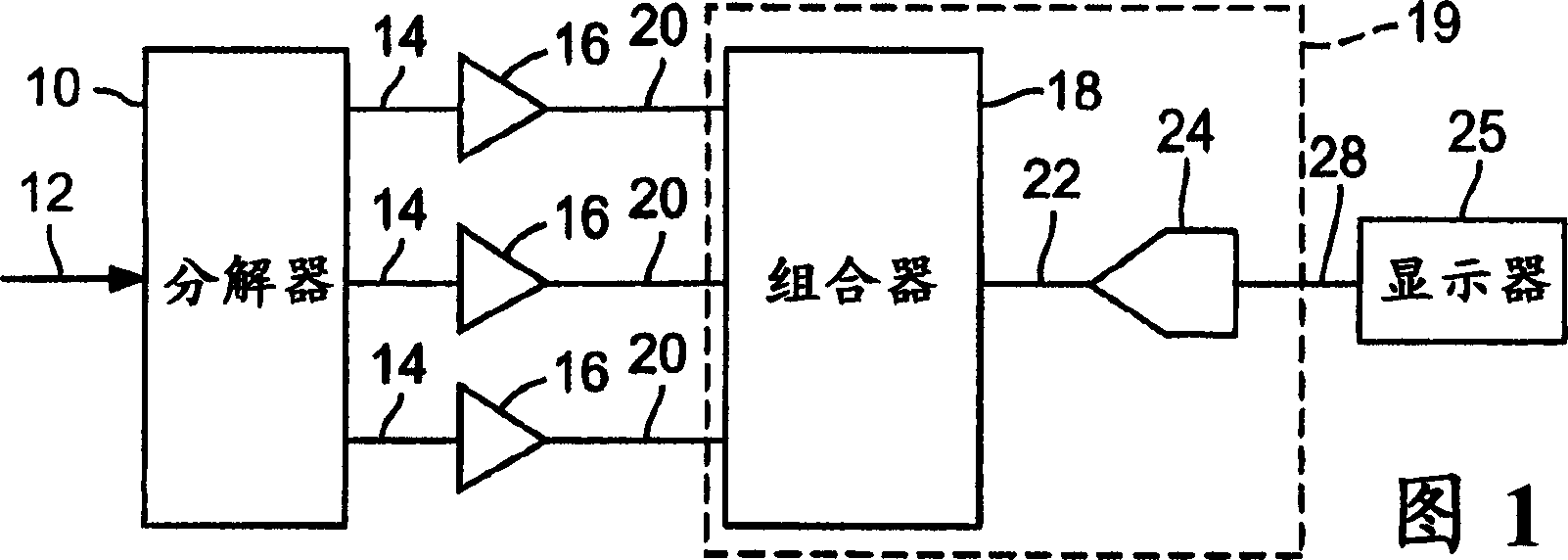
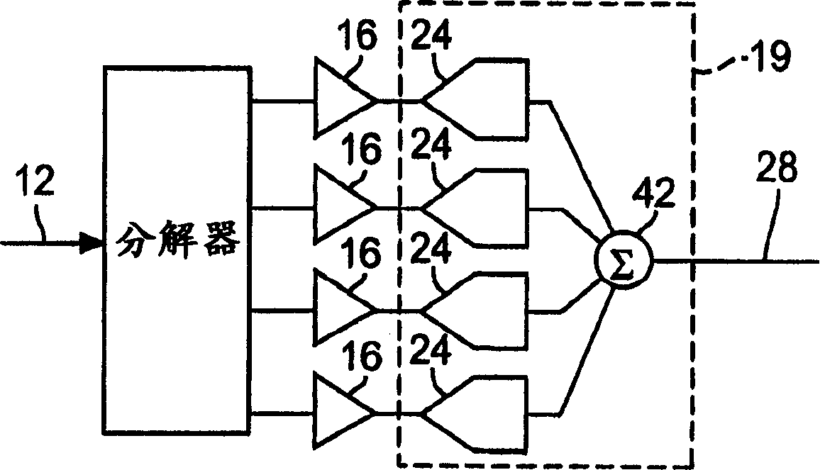
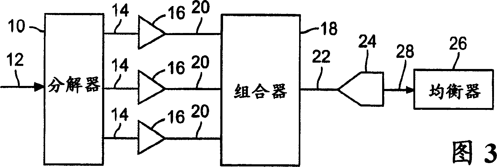
[0020] Figure 1 is a block diagram of a multiband amplifier for test and measurement instruments. The multiband amplifier comprises a resolver 10 , a plurality of amplifiers 16 , means for combining and digitizing 19 and a display 25 .

[0021] The splitter 10 splits the input signal into a plurality of split signals 14 . The resolver 10 may be a multi-channel power divider. One example of a multi-channel power divider is a resistive power divider or resistive power divider. The advantage of the resistive power splitter is that it provides a good 50 ohm input impedance at the input of the resolver 10 over a wide bandwidth. Furthermore, the input and output of the resolver are somewhat isolated from each other due to the inherent power dissipation of the resistive power divider. The amount of this isolation depends on the number of outputs and the split ratio of the outputs. This isolation reduces the effect of any undesirable input impedance of any component connected to t...


PUM


Abstract

A multiband amplifier for a test and measurement instrument includes a splitter to split an input signal into split signals, amplifiers, and means for combining and digitizing the amplified signals into a digitized signal. Each amplifier is configured to amplify an associated split signal over an amplifier passband. The amplifier passband of at least one amplifier is different from the amplifier passband of another amplifier.

Description

[0001] Cross References to Related Applications [0002] Pursuant to 35 U.S.C. §119(e), this application claims priority to U.S. Provisional Application Serial No. 60 / 676,376, filed April 29, 2005, the entire contents of which are hereby incorporated by reference into In this article. technical field [0003] The present invention relates to test and measurement instruments, and more particularly, to multiband amplifiers for test and measurement instruments. Background technique [0004] High quality audio amplifier systems have been working with multiband amplifier architectures for many years. A major reason for this phenomenon is that it is difficult to design a single loudspeaker that can cover the entire audio frequency band. Therefore, different speakers can be used to cover each part of the audio spectrum. However, there are other benefits to be gained by using this structure compared to a single high power amplifier, for example, more headroom can be gained in the...

Claims


Application Information

Patent Timeline
IPC IPC(8): G01R1/30H03F1/42
Inventor J·J·皮克尔德T·F·莱尼汉
Owner TEKTRONIX INC
Why Eureka
Try Eureka