
Image fuzzy correcting system of camera

A blur correction, image technology, applied in the direction of camera, image communication, TV system components, etc., can solve the problems of release time lag growth, power consumption increase, release time lag, etc., to reduce power consumption, prevent The effect of poor focus accuracy

Inactive Publication Date: 2006-11-01
ALPS ALPINE CO LTD
View PDF1 Cites 5 Cited by
  • Summary
  • Abstract
  • Description
  • Claims
  • Application Information

AI Technical Summary

Problems solved by technology

Therefore, in the image blur correction, the driver is driven in order to move the correction lens, so there is a possibility that the accuracy of the focusing process will decrease, and there is a problem that the peak value of the power consumption amount increases.
[0013] In addition, since Patent Document 2 performs image blur correction based on the shooting preparation operation, if focus processing is performed during this image blur correction, the accuracy of focus processing may decrease as in Patent Document 1.
[0014] Furthermore, in Patent Document 2, the image blur correction is performed by a predetermined operation different from the shooting start operation, so the image blur correction is also performed until the start of the shooting preparation operation, so there is a problem of increased power consumption.
[0015] In addition, in Patent Document 3, image blur correction is started based on an instruction to start exposure. Therefore, even if an instruction to start exposure is issued, the image blur correction period becomes an exposure standby state, and the release time, which is the time required from pressing the shutter button to the actual start of exposure, lags. (timelag) growing problem
[0016] Also, in Patent Document 4, image blur correction is not started unless a predetermined time period has elapsed from the shooting preparation operation.
Therefore, even if the focusing process ends earlier than the predetermined time set in advance, the start of the image blur correction is waited until the predetermined time elapses, so there is a problem that the release time lag increases.

Method used


Image

  • Image fuzzy correcting system of camera
  • Image fuzzy correcting system of camera

Examples


Embodiment Construction

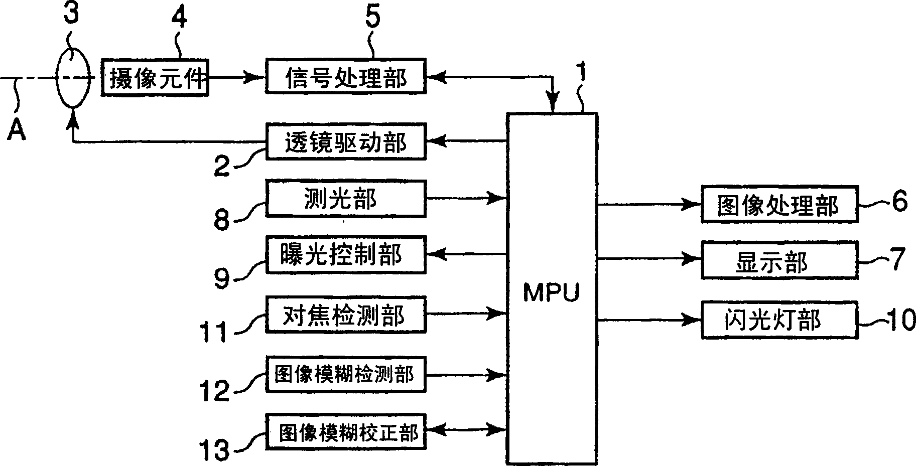
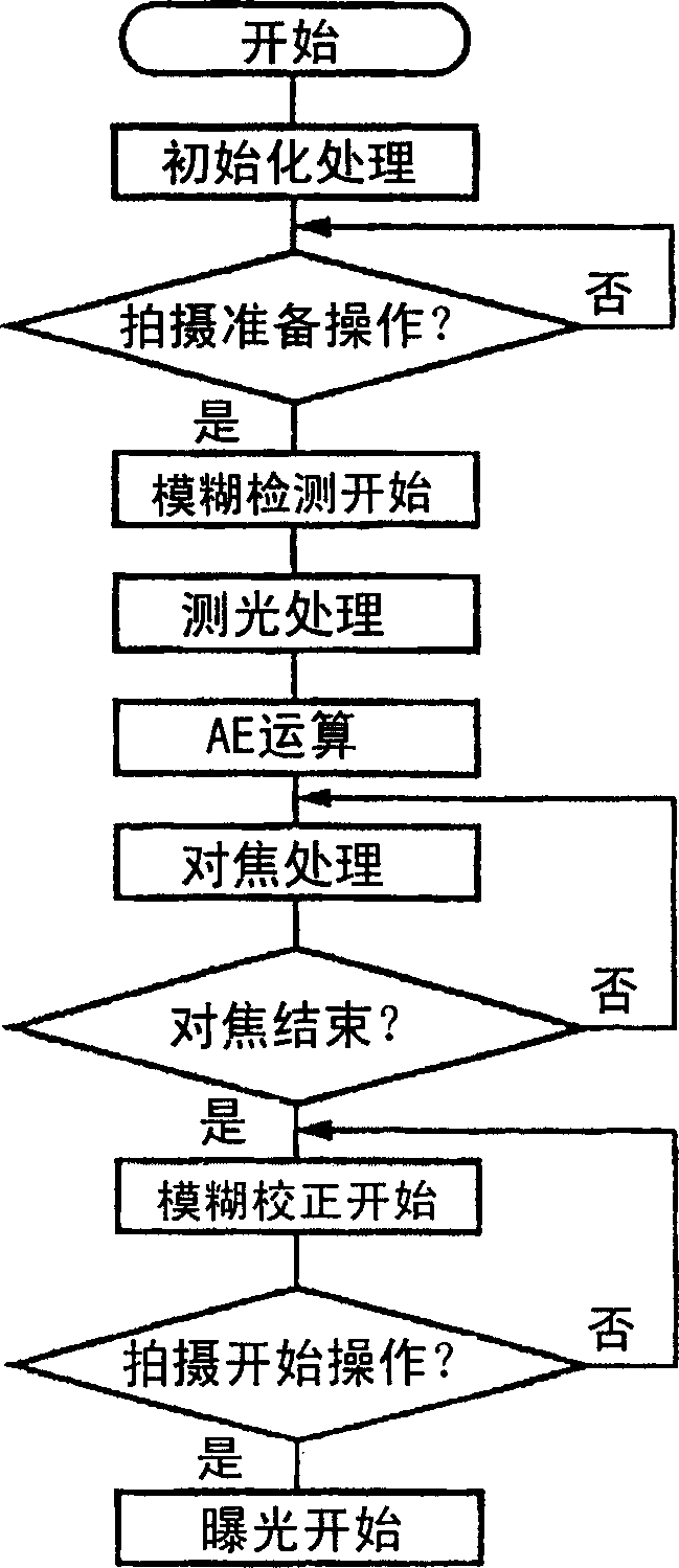
[0027] According to figure 1 , figure 2 Describes an embodiment of the image blur correction system of the present invention. figure 1 Is a block diagram illustrating the general structure of the camera related to the present invention, figure 2 It is a flowchart explaining the procedure of the image blur correction of the present invention.

[0028] First of all, the outline structure of a camera equipped with the image blur correction system of the camera of the present invention, such as a digital camera, such as figure 1 As shown, it has the following structure: an MPU (microprocessor unit) 1 that manages the control of the camera is provided in the camera, and drives the driver of the lens driving section 2 based on a signal from the MPU1, which is supported by the lens barrel The lens 3 moves in the optical axis A direction.

[0029] In addition, the light entering the camera via the lens 3 is stored in the imaging element (CCD) 4 as electric charge, and the image signal ...


PUM


Abstract

There is provided a high-performance image-burr correcting system of a camera, which can improve precision of a focusing process, accomplish low power consumption, and shorten a release time lag. The image-burr correcting system includes an image-burr detecting unit which can detect image burr generated upon photographing; an image-burr correcting unit which can correct the image burr based on the image-burr detection result of the image-burr detecting unit; and a focusing detecting unit which can detect the focused result. After the completion of an appropriate focusing process is detected by the focusing detecting unit, the image-burr correcting unit is driven and image-burr correction is performed in correspondence with an image burr amount detected by the image-burr detecting unit.

Description

Technical field [0001] The present invention relates to an image blur correction system of a camera, and relates to an image blur correction system of a camera that corrects the image blur of the camera caused by hand shake or the like. Background technique [0002] Various proposals for image blur correction systems of cameras for correcting image blur caused by hand shake have been proposed from the past. [0003] If patent documents 1 to 4 are used to outline these various proposed past image blur correction systems, patent document 1 (Japanese Patent Publication No. 07-117676) discloses, for example, shooting by half-pressing the shutter button Prepare for operation, start focus processing and image blur correction. [0004] In addition, in Patent Document 2 (Japanese Patent No. 2752073), it is disclosed that the image blur correction is started according to the shooting preparation operation of half-pressing the shutter button, and in Patent Document 2 it is disclosed that t...

Claims


Application Information

Patent Timeline
Patent Type & Authority Applications(China)
IPC IPC(8): H04N5/243G03B5/00G03B7/30H04N5/232
CPCH04N23/67
Inventor 山县一芳田端正史
Owner ALPS ALPINE CO LTD
Learn More