Panoramic video system with real-time distortion-free imaging

A panoramic video, distortion-free technology, applied to the components of TV systems, TVs, image communications, etc., can solve the problems of time-consuming computer programs, reducing the quality of flat images, and distortion

Inactive Publication Date: 2006-11-01
PHYSICAL OPTICS CORP
View PDF1 Cites 17 Cited by
  • Summary
  • Abstract
  • Description
  • Claims
  • Application Information

AI Technical Summary

Problems solved by technology

The image of the 360° viewing angle lens is circular or ring-shaped and therefore distorted, and it is not easily discernible by a human observer
The unwrapping process involves mathematical transformations such as conversions of each picture element or pixel, and is preferably done in a manner that produces little or no distortion that would otherwise degrade the quality of the resulting planar image
Typically, this pixel-by-pixel conversion is very complex and requires complex and time-consuming computer programs, especially for images with reasonable levels of resolution and large numbers of pixels
Therefore, it is not possible to use panoramic lens technology to provide real-time unwrapped video images with desirable resolution

Method used


Image

  • Panoramic video system with real-time distortion-free imaging
  • Panoramic video system with real-time distortion-free imaging
  • Panoramic video system with real-time distortion-free imaging

Examples


Embodiment Construction

[0034] Panoramic Ring Lens (PAL)

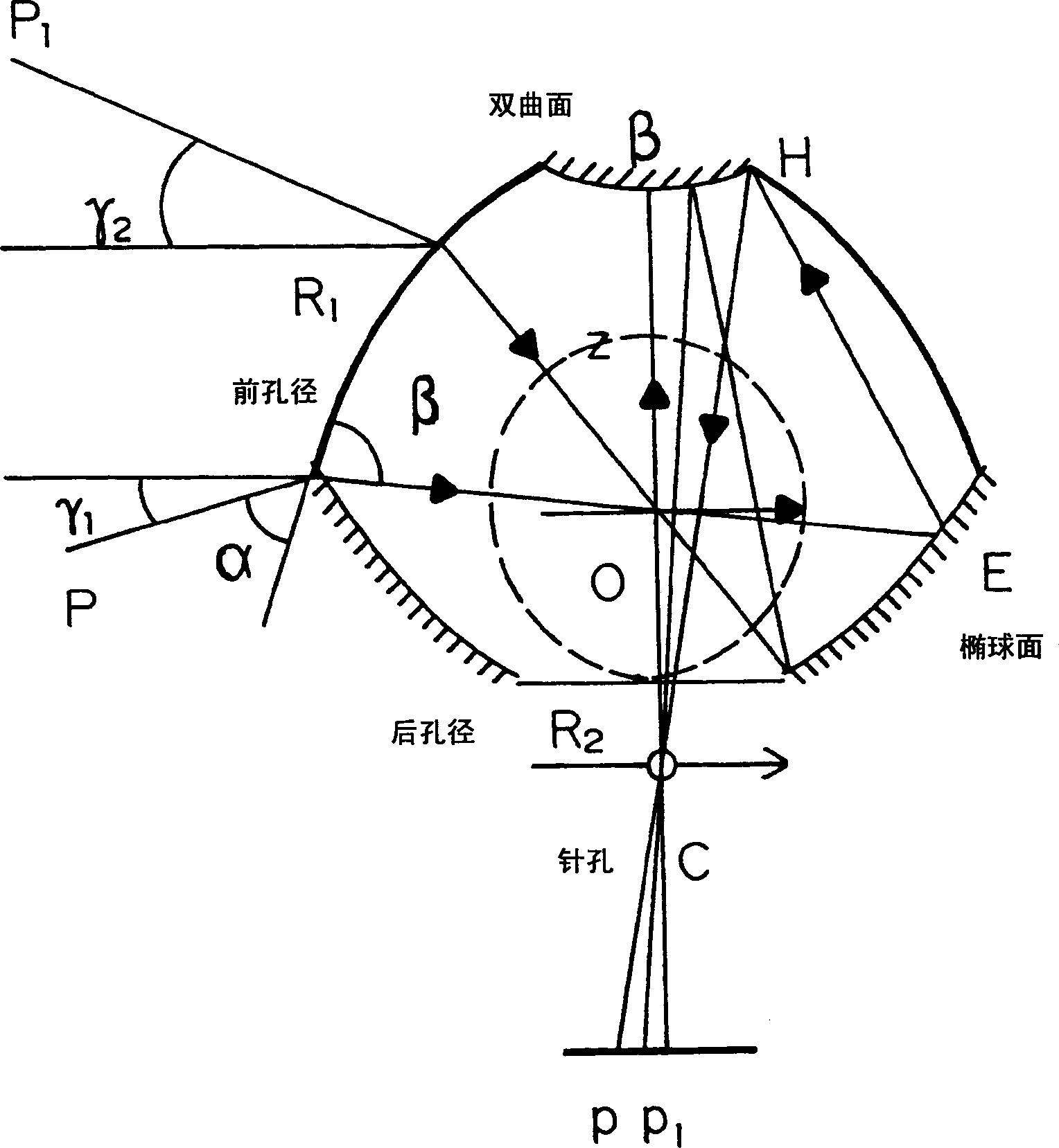
[0035] PAL lenses are based on the reflection and refraction of light, and provide a panoramic 360° viewing angle in an ultra-compact package with a diameter of only 40mm. PAL lenses provide, for example, -40° to +50° vertical field of view. Such as figure 1 As shown, the panoramic lens is a piece of glass consisting of a 360° circular aperture (R1), a rearward aperture (R2) connected to a condenser lens, a top mirror (H) and a circular mirror (E). The observation point of the "vertical camera" is on the plane (O) of the ellipsoidal mirror (E). With this geometry, the PAL sensor can see the entire 360° scene around its vertical axis BC. The position field of view is determined by the effective size and vertical of the circular mirror E and the top mirror H. Usually the viewing angle is 90° vertical.

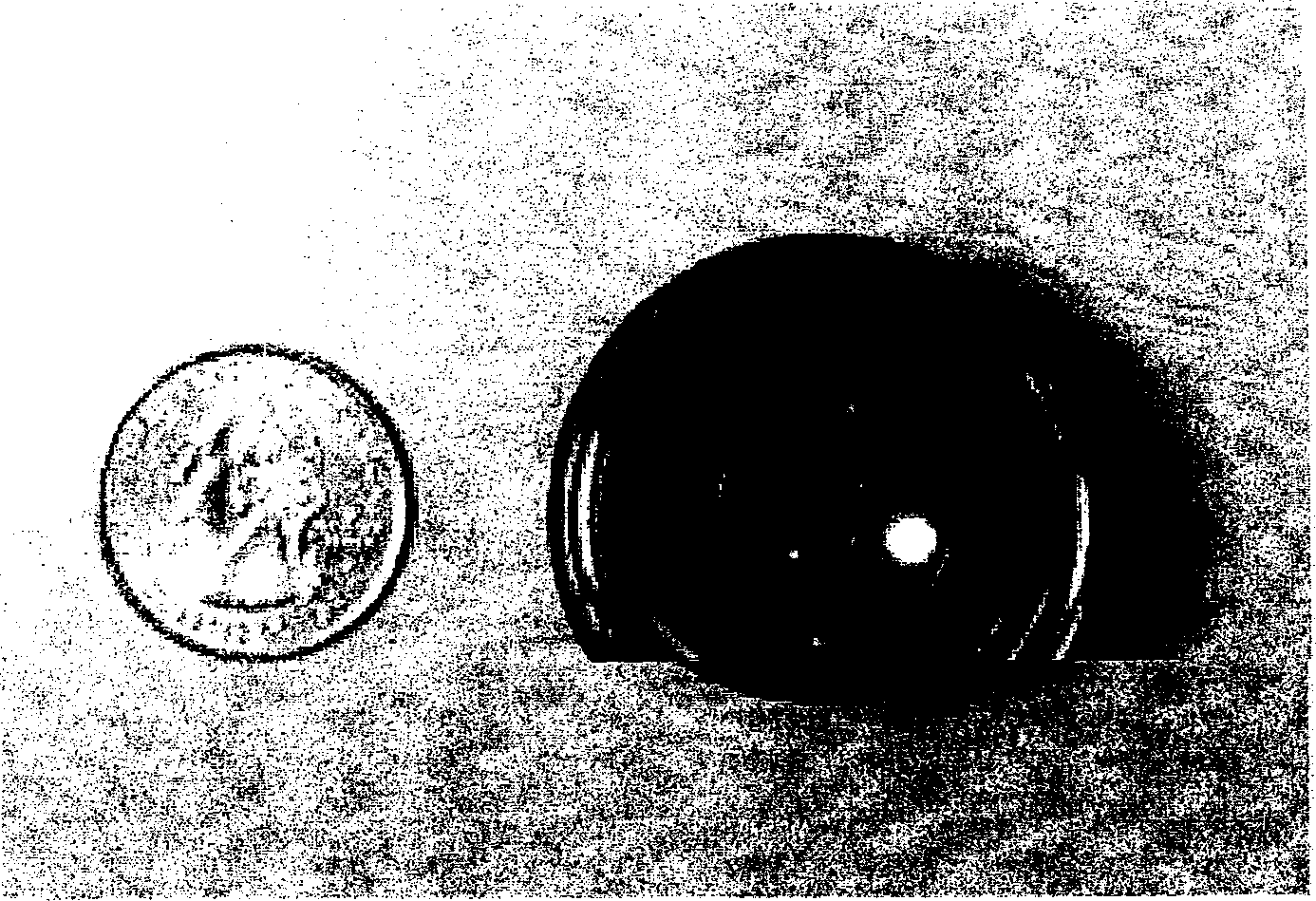
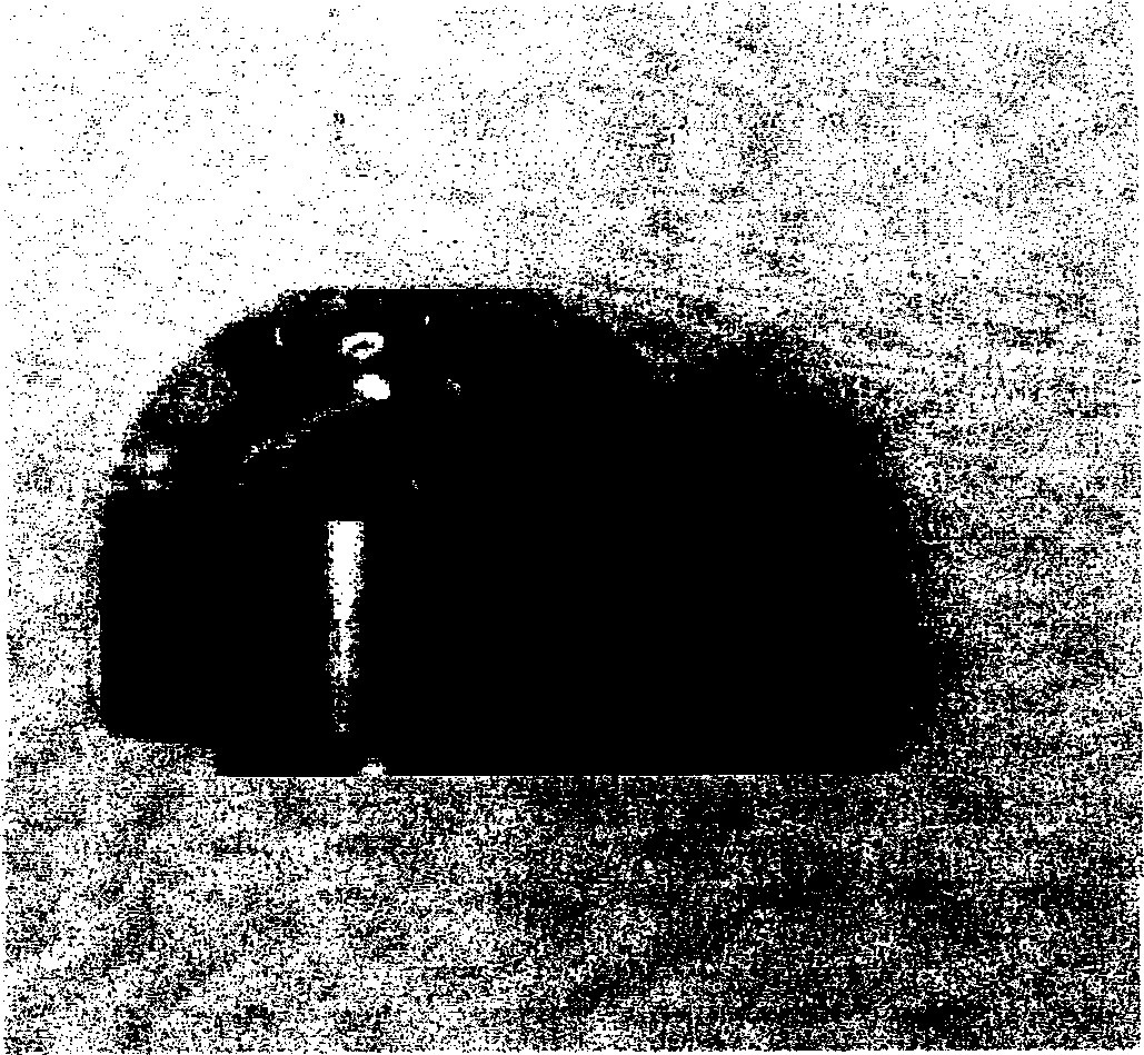
[0036] Figure 2a and 2b PAL is shown. To maintain a wide range of camera angle options, terminate the PAL mount with a C-mount that fi...


PUM


Abstract

A panoramic annular lens system (PAL), a unitary video camera and a PCbased software system that unwraps a 360 DEG video image into a seamless, distortion free horizontal image in real time. The PAL system of the preferred embodiment has a 360 DEG horizontal field of view and a 90 DEG vertical field of view in a 40mm diameter compact package. The invention is not limited to any particular type of lens system. In fact, there are numerous lens systems for providing a 360 DEG panoramic view. The video camera may be a CCD or CMOS based device having a pixel resolution of either 1280 x 1024 (high resolution) or 720 x 480 (NTSC). The unwrapping system is a radiometric ray tracing program carried out using a computer's graphics card capabilities to produce highly efficient regional transformation while minimizing software overhead. The result is real time, high resolution 30 fps conversion from a spherical distorted image to a flat panoramic image in Cartesian coordinates.

Description

[0001] Work on this invention was performed under USMA Contract No. M67854-03-C-1006, and the contractors elect to retain rights as set forth in Publication Code Section 96-517 (35 USC 202). technical field [0002] The present invention relates generally to the field of special camera systems, and more specifically, to a real-time 360° panoramic video system using panoramic loop mirrors, cameras and unique deployment software, providing a seamless, undistorted horizontal view of the panoramic image. [0003] This application claims priority to Provisional Application Serial No. 60 / 485,336, filed July 3,2003. Background technique [0004] Panoramic optical systems are known which can be used to provide a 360° viewing angle. As an example, U.S. Patent No. 6,459,451 discloses a catadioptric lens that provides a 360° viewing angle. Such optical systems can be advantageously used with cameras to provide a system capable of imaging a full 360° view of eg an entire room or a view...

Claims


Application Information

Patent Timeline
Patent Type & Authority Applications(China)
IPC IPC(8): H04N5/225
Inventor 安德鲁·A·科斯切夫斯基鲁守康伊利亚·阿居罗克马克·本纳汉斯
Owner PHYSICAL OPTICS CORP
Why Eureka
Try Eureka