Ventilation skylight

A ventilator and ventilation device technology, applied in the field of roof ventilation skylights, can solve the problems of large motor load, inflexible opening and closing, and inability to adjust the upper and lower positions of the valve plate, so as to improve work efficiency, flexible opening and closing of the valve plate, and shorten the movement the effect of time

Inactive Publication Date: 2006-11-08
孙建和
View PDF1 Cites 5 Cited by
  • Summary
  • Abstract
  • Description
  • Claims
  • Application Information

AI Technical Summary

Problems solved by technology

CN03268797.4 discloses a combined roof ventilator. This ventilator mainly adopts a V-shaped valve plate structure, and the pull rope directly pulls the valve plate to realize the opening and closing function. This structure cannot adjust the upper and lower positions of the entire valve plate, and The motor load is heavy, and the opening and closing is not flexible enough

Method used


Image

  • Ventilation skylight
  • Ventilation skylight
  • Ventilation skylight

Examples


Embodiment Construction

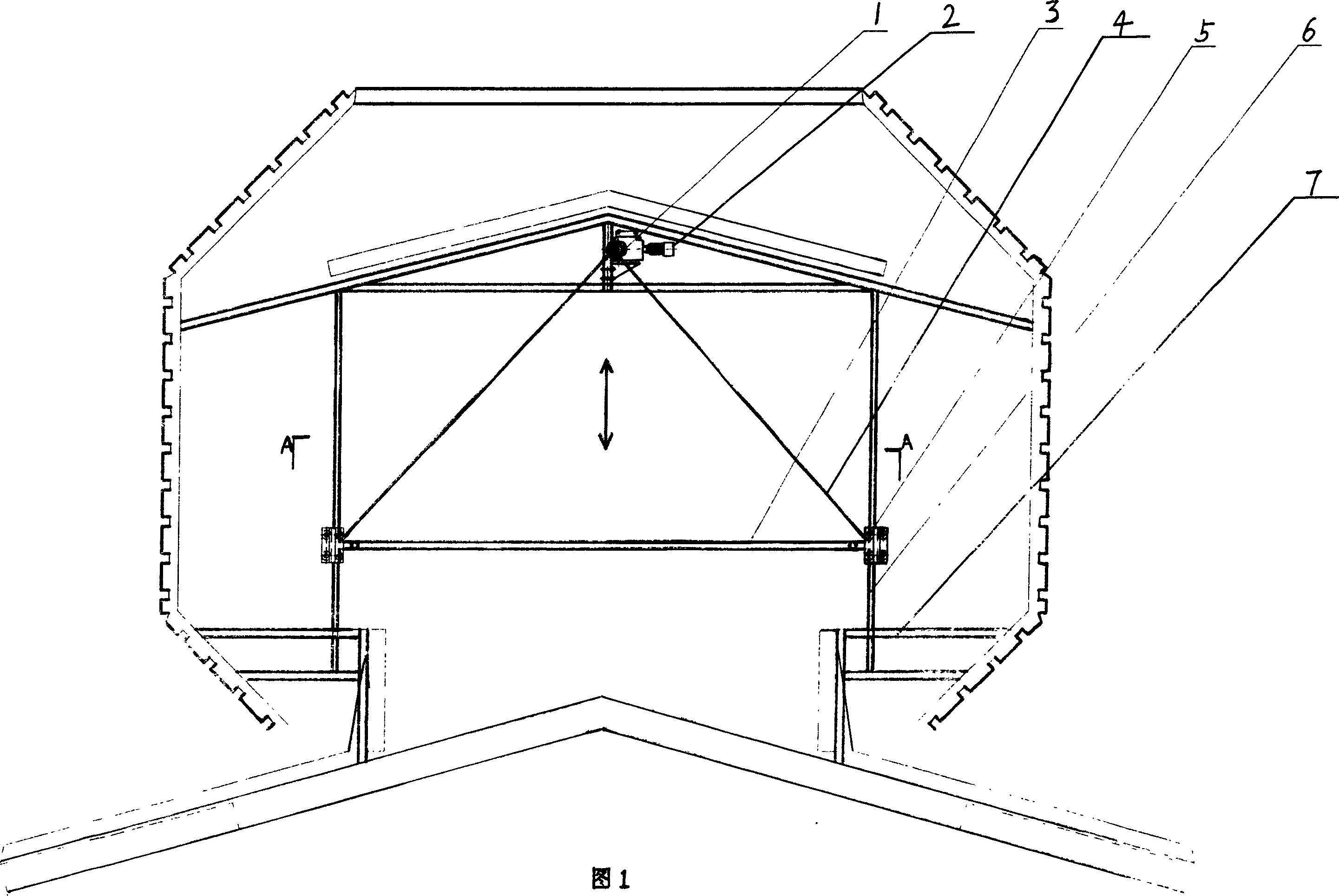
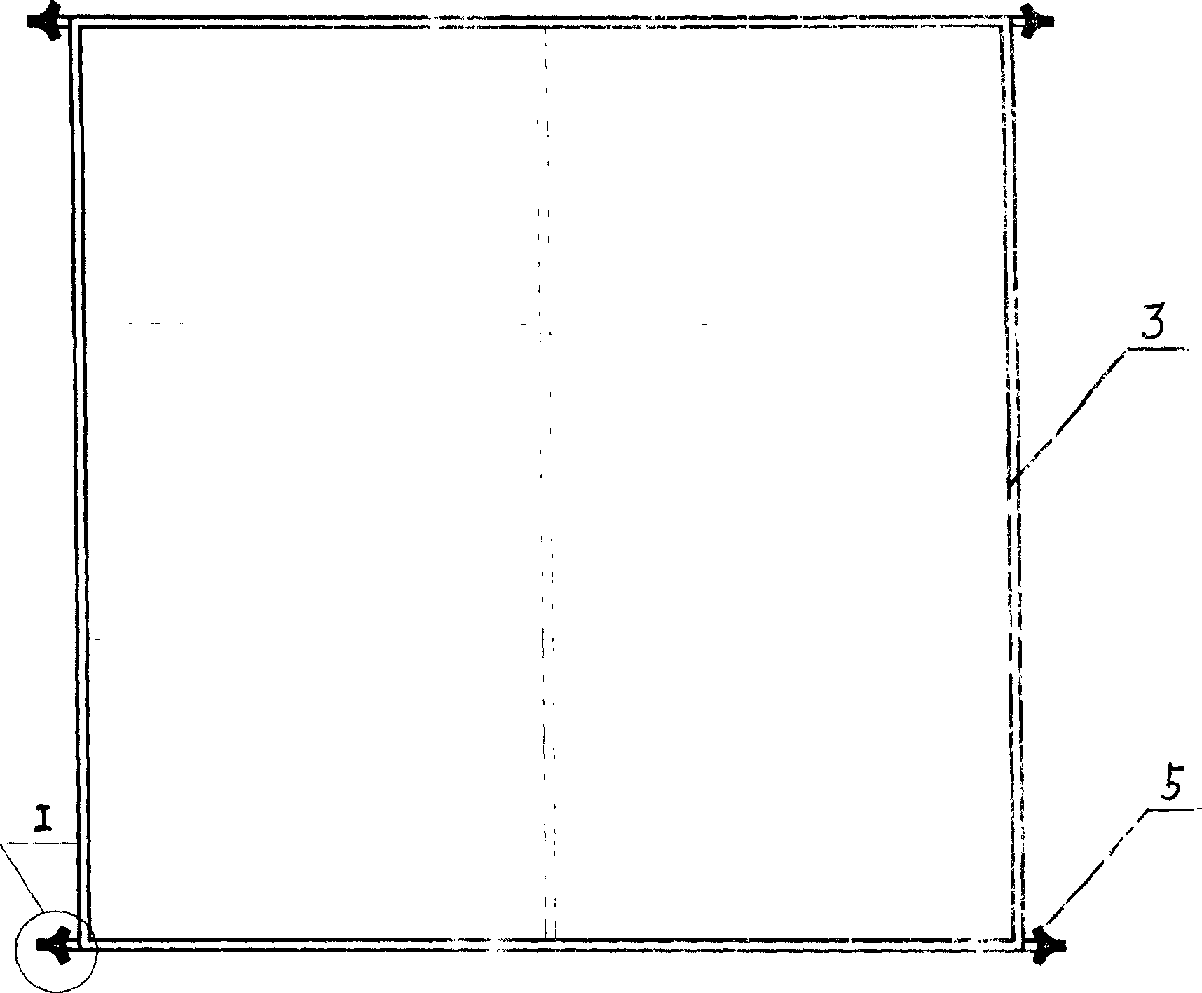
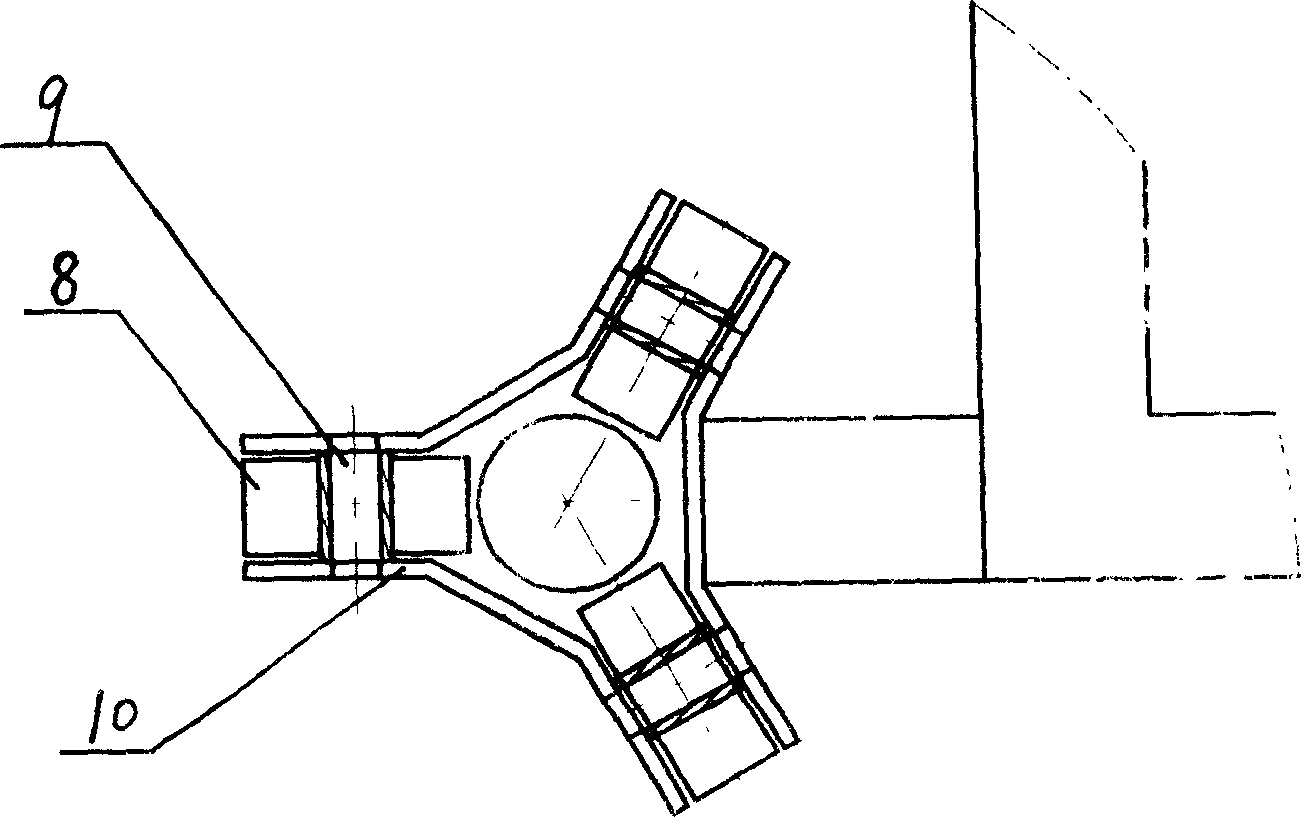
[0010] It can be seen from Figure 1 that the present invention includes a ventilator frame 7, a valve plate 3 located at the throat, and an electric opening and closing mechanism. The valve plate 3 is realized by the electric opening and closing mechanism. The electric opening and closing mechanism is composed of a motor 2 and a reducer. 1. Consists of a limit device 5 and a draw rope 4. The limit device 5 is fixedly connected to the end of the valve plate 3, and the limit device 5 is movably sleeved on the guide frame 6, so that the valve plate 3 can move up and down along the guide frame 6. , The guide frame 6 is installed and fixed on the ventilator frame 7. When the motor 2 rotates clockwise or counterclockwise, the opening and closing function of the valve plate 3 is realized through the pulling of the transmission mechanism and the pull rope 4, and the upper and lower positions of the entire valve plate of the ventilation skylight can be adjusted to improve the flow state of...


PUM


Abstract

The ventilation skylight includes ventilator frame, valve plate in the throat part and electric opening-closing mechanism. The electric opening-closing mechanism consists of motor, speed reducer, limiter and pull rope. The limiter is connected to the end of the valve plate and movably on a guide body mounted on the ventilator frame, so that the valve plate may be shifted vertically along the guide body. The present invention can regulate the vertical position of the valve plate, and flexible opening and closing of the ventilation skylight.

Description

Technical field [0001] The invention relates to a ventilation device, in particular to a roof ventilation skylight used in a high-heat factory building. Background technique [0002] At present, combined roof ventilation skylights are mostly used for natural ventilation equipment in high-heat workshops. This type of ventilation skylights are mainly composed of peripheral guards, rain shields, flooding plates, and valve plates. Many manufacturers have been able to use electric mechanisms to Realize the opening and closing of the valve plate, and always realize the ventilation performance of the workshop. CN03268797.4 discloses a combined roof ventilator. This ventilator mainly adopts a V-shaped valve plate structure. The valve plate is directly drawn by a rope to realize the opening and closing function. This structure cannot adjust the upper and lower positions of the entire valve plate, and The motor load is large, and the opening and closing is not flexible enough. Summary of ...

Claims


Application Information

Patent Timeline
Patent Type & Authority Applications(China)
IPC IPC(8): F24F7/02
Inventor 孙建和蔡鹏顾林根姚建勋
Owner 孙建和
Why Eureka
Try Eureka