Loading, detecting and monitoring method for optical associated channel signal and its realizing device

A technology of channel-associated signals and loading devices, applied in electromagnetic wave transmission systems, electrical components, transmission systems, etc., can solve problems such as inability to carry channel-associated overhead, influence of main optical service signals, low-frequency signal energy concentration, etc., to increase the judgment network Effects of degradation, reduction of implementation cost, and reduction of detection difficulty

Active Publication Date: 2006-11-08
HUAWEI TECH CO LTD
View PDF5 Cites 21 Cited by
  • Summary
  • Abstract
  • Description
  • Claims
  • Application Information

AI Technical Summary

Problems solved by technology

Although US5513029 can realize the monitoring of optical signal quality, it has several disadvantages: 1. Different wavelengths must use different frequencies for identification, and the frequency interval must be greater than the frequency resolution of the monitoring point, so the available identification signals are very limited; 2. Although the low-frequency disturbance signal has little effect on the quality of the main optical service signal, the low-frequency disturbance signal still has a certain impact on the main optical service signal; 3. The corresponding relationship between the wavelength signal and the low-frequency signal must be configured in advance, otherwise it is impossible to know which channel is being monitored wavelength optical signal; 4. This method cannot carr

Method used


Image

  • Loading, detecting and monitoring method for optical associated channel signal and its realizing device
  • Loading, detecting and monitoring method for optical associated channel signal and its realizing device
  • Loading, detecting and monitoring method for optical associated channel signal and its realizing device

Examples


Embodiment Construction

[0074] Preferred embodiments of the present invention are described in detail below.

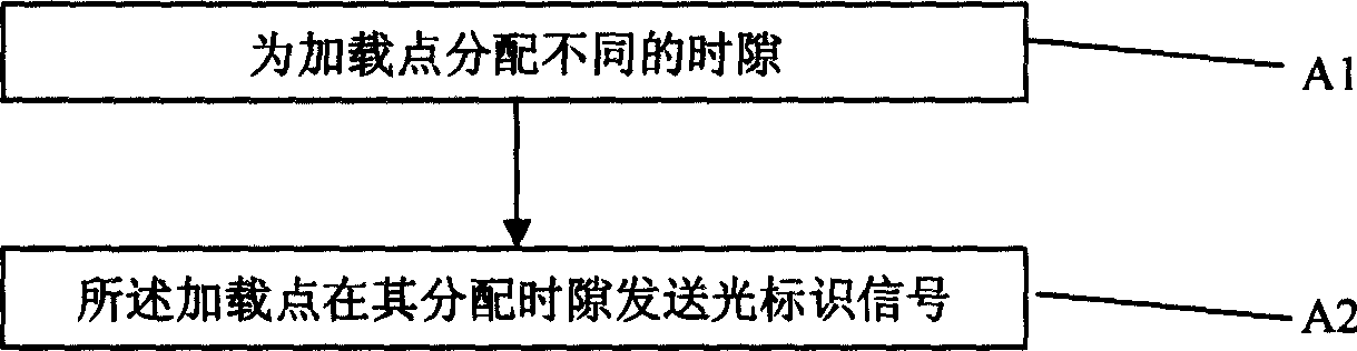
[0075] The invention provides a method for loading optically-associated signals, as shown in the attached figure 1 As shown, it includes steps: A1, assigning different time slots to the loading point; A2, the loading point sends an optical identification signal in its assigned time slot. The method for allocating time slots is static allocation or dynamic allocation.

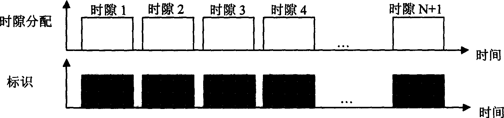
[0076]First, different time slots A1 are allocated to loading points; time slots may be allocated to each loading point, so that each loading point has a different time slot. There is a time interval between identification signals sent by different loading points, and the time interval is used to avoid identification conflicts. Since there is a certain delay between the loading points, when assigning time slots, a certain time slot interval can be reserved in advance, and the loading point does not load the identification si...


PUM


Abstract

This invention provides a loading, testing and monitoring method for optical associated signals and its device, in which, the loading method includes: A1, distributing different time slots for loaded points, A2, each loaded point sends optical identification signals at the corresponding distribution time slot, the test method includes: B1, splitting the optical signals into two paths of signals, B2, converting a path of optical signals to corresponding electric signals, B3, separating the electric signals and picking up the identification signals from them.

Description

technical field [0001] The present invention relates to a communication system optical identification signal method and its implementation device, in particular to a method for loading, detection and monitoring of an optical accompanying signal, and its implementation device. Background technique [0002] The advancement of optical devices has greatly promoted the development of optical communication. With the maturity of reconfigurable optical devices such as Wavelength Blocker (WB, Wavelength Blocker) and Wavelength Selective Switching (WSS, Wavelength Selectvie Switching), it has become possible to construct an optical transport network based on all-optical signal processing. However, due to the transparency of the optical signal, it cannot carry the associated overhead information. Without the support of on-road overhead, on the one hand, the quality of the optical signal cannot be monitored throughout the process, and corresponding processing measures cannot be taken a...

Claims


Application Information

Patent Timeline
IPC IPC(8): H04B10/079
Inventor 常天海曾远宏扶文忠靳玉志黄志勇陈娟李从奇
Owner HUAWEI TECH CO LTD
Why Eureka
Try Eureka