Dehumidifier water tank with draining structure

A drainage structure and dehumidifier technology, applied in the direction of preventing condensed water, household heating, lighting and heating equipment, etc., can solve the problems of users' troubles, the dehumidifier water tank does not have continuous drainage function, etc., and achieve the purpose of improving the convenience of use Effect

Inactive Publication Date: 2006-11-15
LG ELECTRONICS (TIANJIN) APPLIANCES CO LTD
View PDF0 Cites 11 Cited by
  • Summary
  • Abstract
  • Description
  • Claims
  • Application Information

AI Technical Summary

Problems solved by technology

[0015] However, the water tank of the dehumidifier in the prior art does not have the function of continuous drainage, and the water level of the condens

Method used


Image

  • Dehumidifier water tank with draining structure
  • Dehumidifier water tank with draining structure
  • Dehumidifier water tank with draining structure

Examples


Embodiment Construction

[0044] In order to further understand the content, characteristics and effects of the present invention, the following examples are given, and detailed descriptions are as follows in conjunction with the accompanying drawings

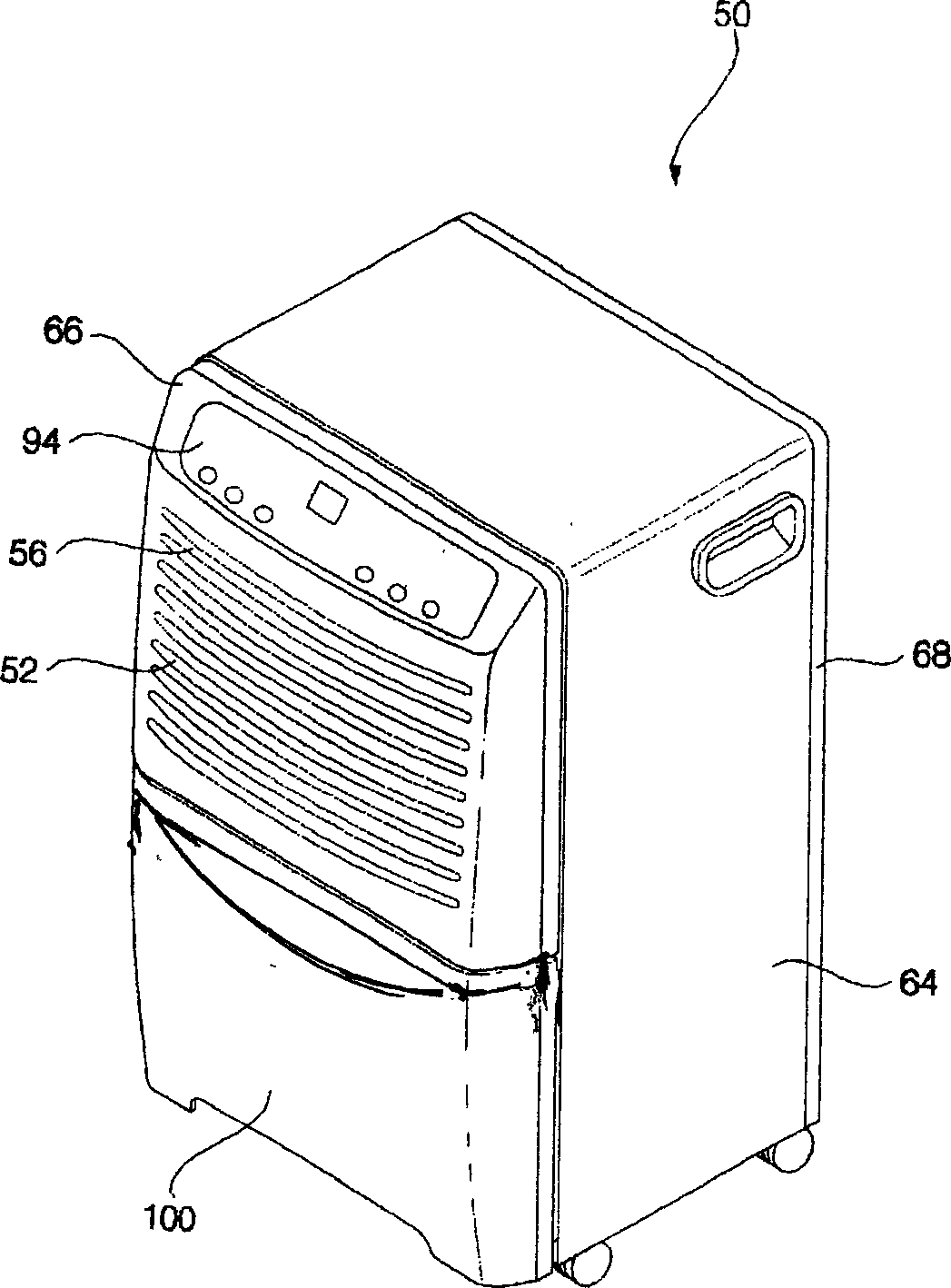
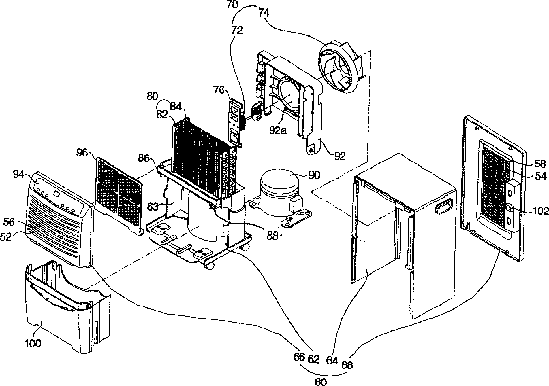
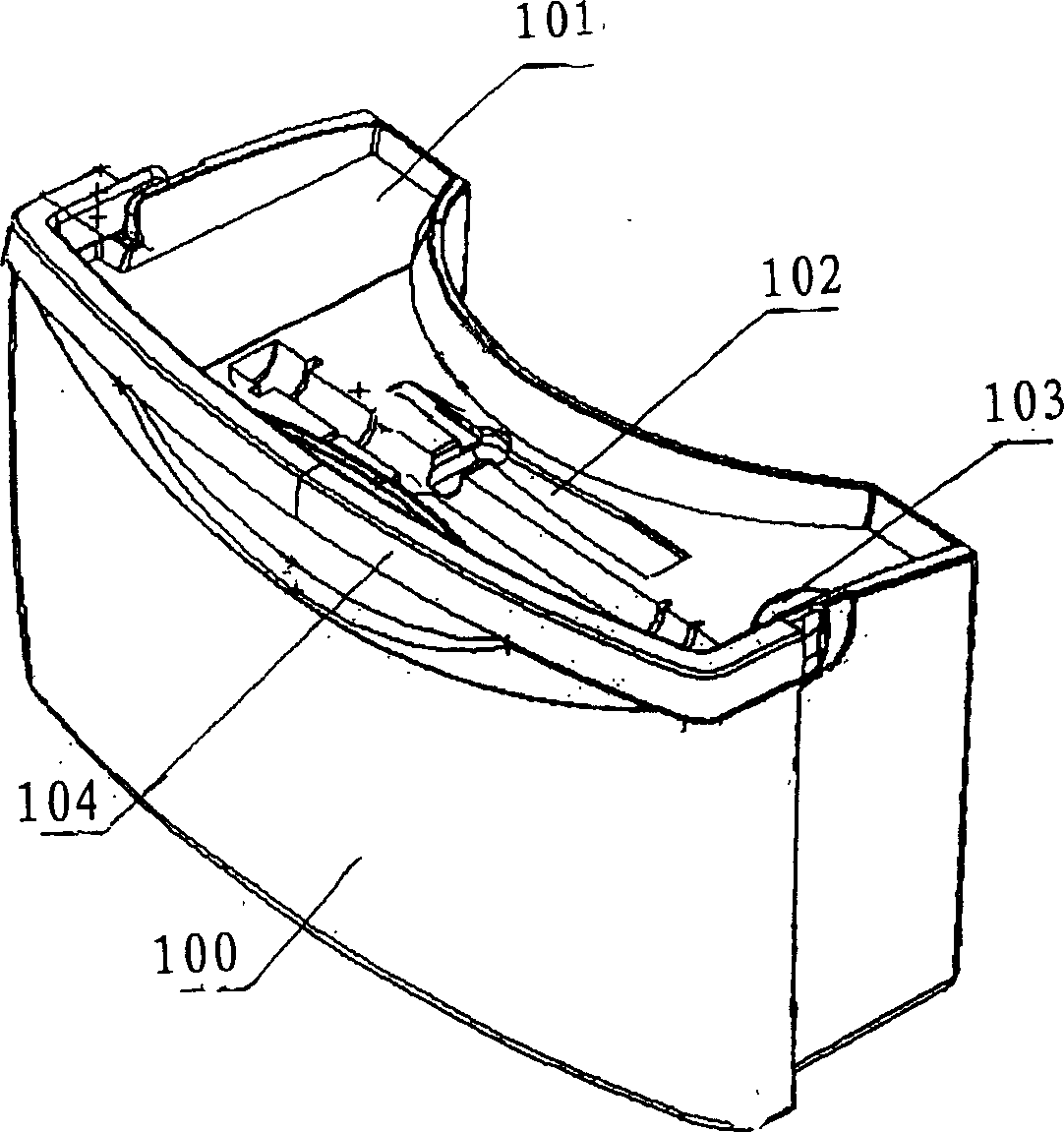
[0045] figure 1 It is the outline drawing of the dehumidifier in the prior art, figure 2 It is an exploded view of a dehumidifier in the prior art, image 3 It is the outline drawing of the dehumidifier water tank in the prior art, Figure 4 It is the outline drawing of the dehumidifier with drainage structure dehumidifier water tank of the present invention, Figure 5 It is the outline drawing of the water tank of the dehumidifier when the drain pipe of the present invention is put down, Figure 6 It is the outline drawing of the water tank of the dehumidifier when the drainage pipe of the present invention is erected.

[0046] A dehumidifier water tank 100 with a drainage structure in the present invention includes a water tank 100 arranged under...


PUM


Abstract

The invention includes a water tank disposed under the drawdown gate of the water plate, a cover surface with grooves, a water tank cover, a water tank handle pulling the water tank outward, an outfall formed at the side bottom of the water tank, a foldable drain-pipe connected with the outfall and connecting members formed on the side of the water tank for hanging the drain-pipe.

Description

technical field [0001] The invention belongs to the technology of dehumidifiers, and in particular relates to a dehumidifier water tank with a drainage structure which can easily convert the drainage operation of condensed water to continuous drainage. Background technique [0002] Generally speaking, the dehumidifier introduces the humid air in the room into the inside of the chassis, reduces the humidity through a heat exchanger composed of an evaporator and a condenser with refrigerant flow, and then discharges the dehumidified air into the room to reduce the humidity of the room. device for humidity purposes. [0003] Dehumidifiers made by previous technologies such as figure 1 and figure 2 As shown, the air intake 52 is mainly formed at the front, and the chassis 60 of the air discharge port 54 is formed at the rear; it is arranged behind the air intake 52 to introduce moist air through the air intake 52 and discharge it to the air discharge port 54 A fan machine 70...

Claims


Application Information

Patent Timeline
IPC IPC(8): F24F3/14F24F13/22
Inventor 杨佩元
Owner LG ELECTRONICS (TIANJIN) APPLIANCES CO LTD
Why Eureka
Try Eureka