
Coding format for passive RF identifying system

A radio frequency identification system and coding format technology, applied in the coding format field, can solve the problems such as the inability to immediately distinguish the position of the starting point of the low-level pulse, increasing the complexity of the PPM demodulation circuit, etc.

Inactive Publication Date: 2006-11-15
HOLTEK SEMICON
View PDF0 Cites 5 Cited by
  • Summary
  • Abstract
  • Description
  • Claims
  • Application Information

AI Technical Summary

Problems solved by technology

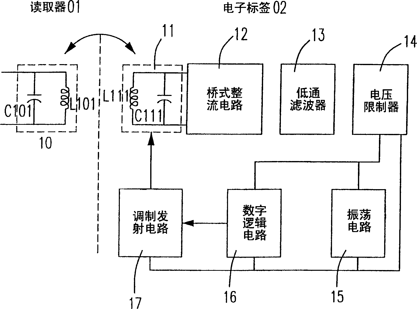
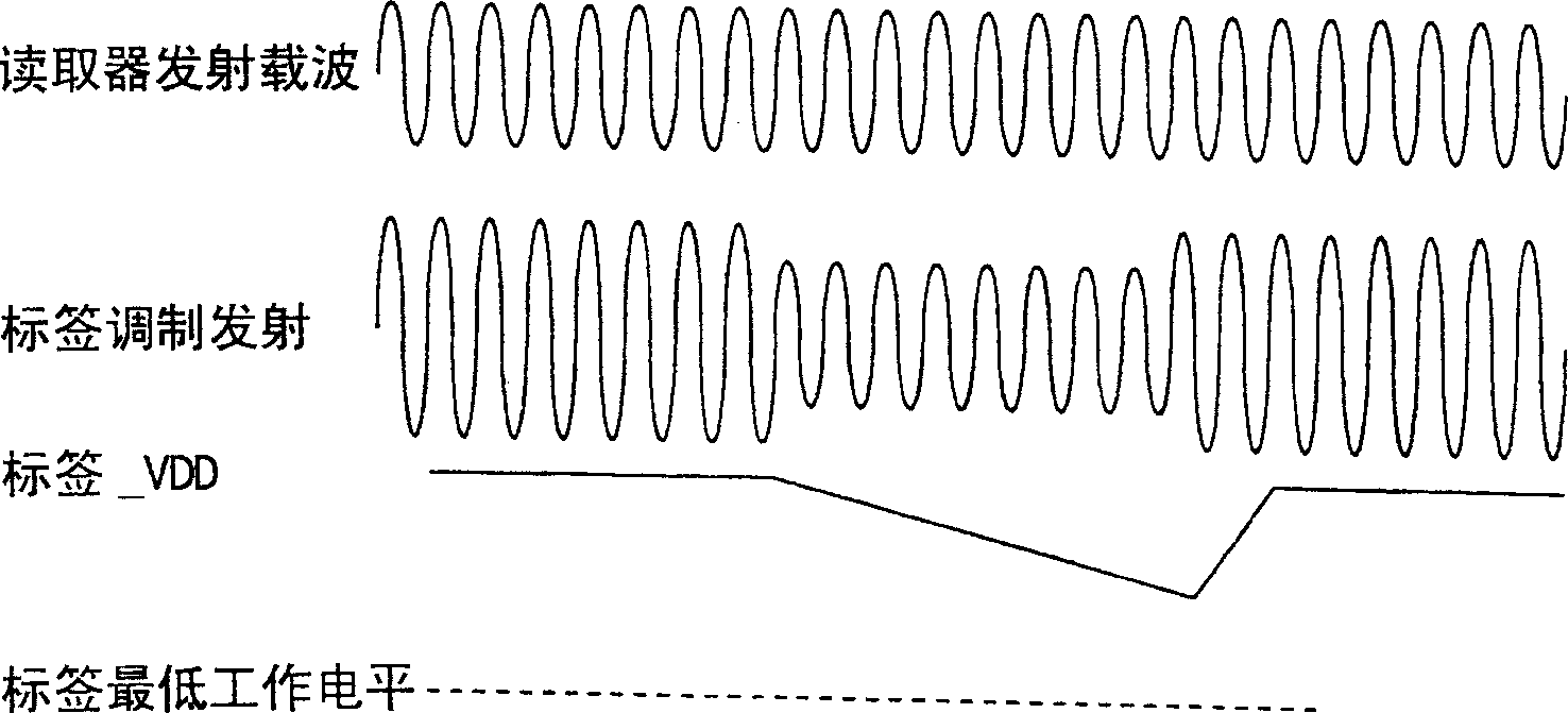
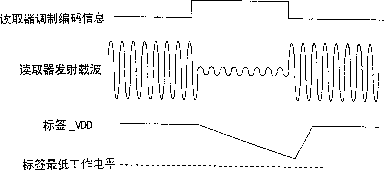
However, in actual operation, it is impossible to immediately distinguish the starting point of the low-level pulse. Therefore, complex position locking actions must be performed to avoid misjudgment, thus increasing the complexity of the entire PPM demodulation circuit.

Method used


Image

  • Coding format for passive RF identifying system
  • Coding format for passive RF identifying system
  • Coding format for passive RF identifying system

Examples


Embodiment Construction

[0049] The invention provides a communication transmission interface suitable for two-way communication in a passive RFID system, which combines the transmission characteristics of PWM and PPM data encoding, adopts the characteristics of PPM single low-level pulse, and has different length encoding characteristics from PWM, and utilizes two discontinuous The distance between a single low-level pulse represents different instructions or data, so as to design a series of specific instructions or data for information transmission.

[0050] see Figure 6 , which is a schematic diagram of data transmission of passive RFID in a preferred embodiment of the present invention. As shown in the figure, all commands and data start with a unit low-level pulse, and the unit length of the subsequent high-level pulse is used to determine whether it represents a command or data, that is, the distance between high-level pulses is used To distinguish different information meanings, it can also ...


PUM


Abstract

The present invention provides a code format of passive radio-frequency identification system, it can be used in a radio-frequency identification system, and contains low-level pulse with one unit length and high-level pulse with n unit lengths, and utilizes regulation of value of n to form different instructions or data formats. The invented code format can be combined with transmission characteristics of PWM and PPM data code and can provide a specific code format so as to make data transmission with specific format protocol. At the same time, it has simple demodulation function, under the condition of limited power supply of passive RFID system can prolong service distance of passive RFID system.

Description

technical field [0001] The invention relates to a coding format, in particular to a coding format applied to a passive radio frequency identification system. Background technique [0002] The passive radio frequency identification (Radio Frequency Identification, RFID) system is limited by the expansion of the application field and cost considerations when performing data transmission, and cannot provide complex communication modulation methods. Therefore, AM (amplitude modulation) is commonly used for data transmission. The electronic tag (tag) end of the passive RFID system has no active power supply, so the power supply at the tag (tag) end can only use the radio frequency (Radio Frequency, RF) sent by the reader (reader). The carrier wave is used as an AC signal for AC / DC power conversion, and data transmission is completed under limited power supply. [0003] In known passive RFID systems, such as figure 1 As shown, electromagnetic mutual induction is performed throug...

Claims


Application Information

Patent Timeline
Patent Type & Authority Applications(China)
IPC IPC(8): G06K19/06H04L27/04
Inventor 许绩贺
Owner HOLTEK SEMICON
Learn More