Supercharge Your Innovation With Domain-Expert AI Agents!

Indicator lamp

A display lamp and lens technology, applied in the field of display lamps

Inactive Publication Date: 2006-11-15
OKAYA ELECTRIC INDS
View PDF1 Cites 41 Cited by
  • Summary
  • Abstract
  • Description
  • Claims
  • Application Information

AI Technical Summary

Problems solved by technology

[0005] In addition, in the conventional lens for light-emitting element, in view of its structure, in order to form a convex portion in the center of the front surface of the lens, a deep annular groove is formed. Difficult, especially in a lens with a high height, the annular groove will become too deep. Due to the size and material of the lens, it may not be able to uniformly and efficiently irradiate the light from the light-emitting element forward

Method used


Image

  • Indicator lamp
  • Indicator lamp
  • Indicator lamp

Examples


Embodiment Construction

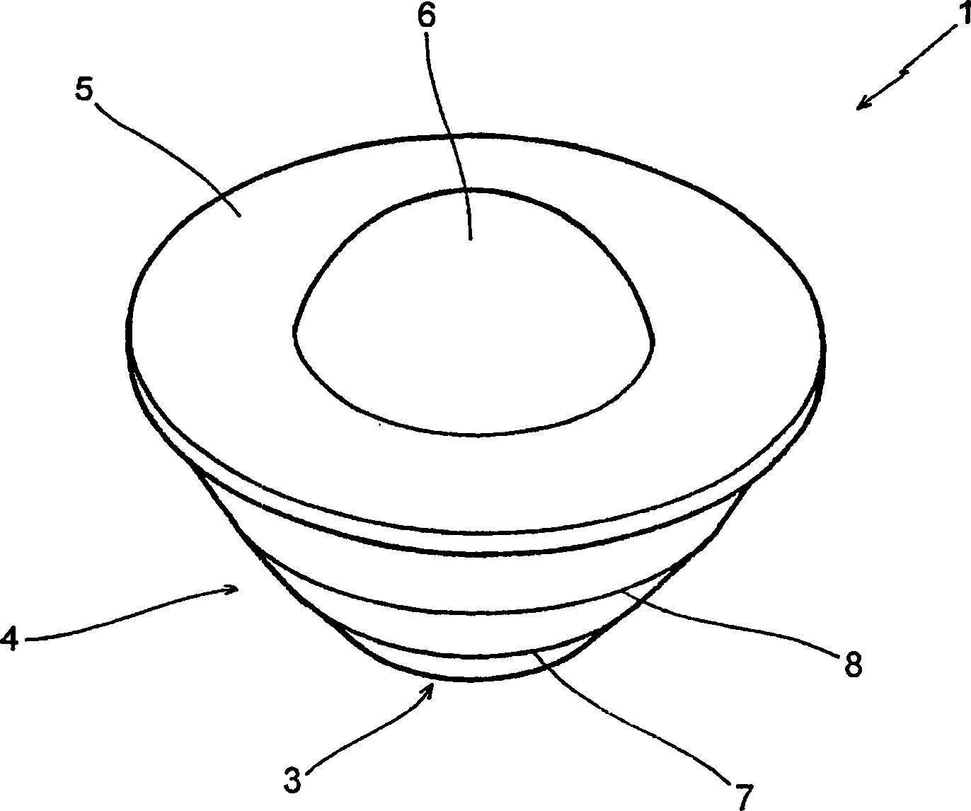
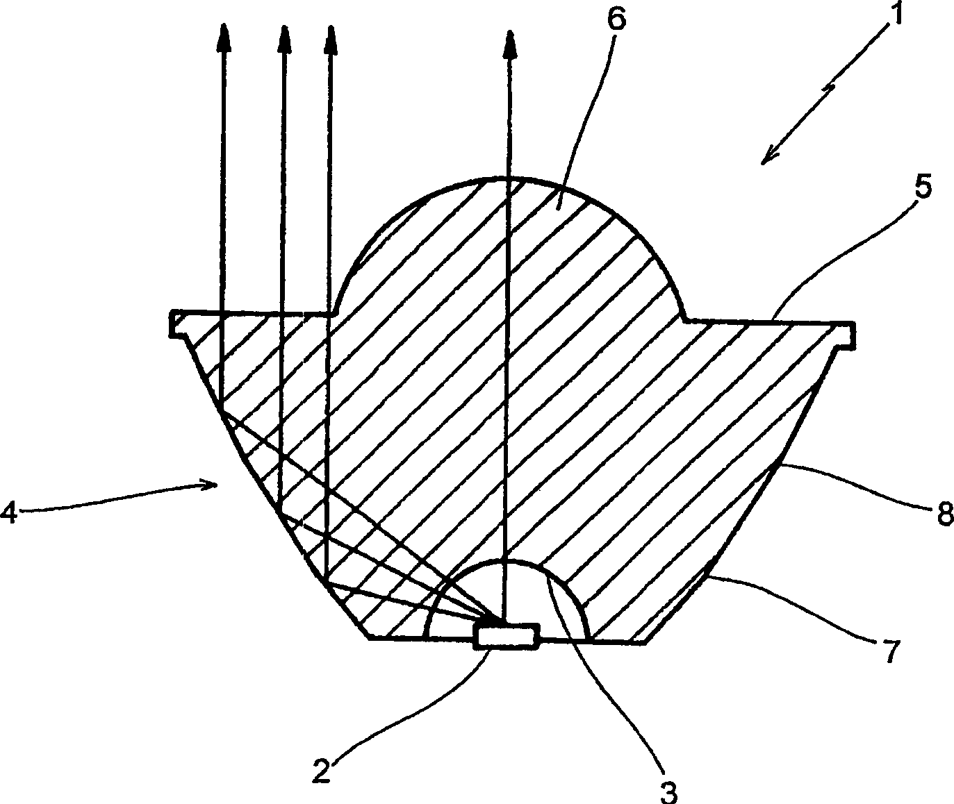
[0027] figure 1 , figure 2 In the display lamp showing the first embodiment of the present invention, the lens 1 for a light-emitting element obtained by forming a transparent synthetic resin material into an approximately truncated cone shape has a light-emitting element mounting portion 3 for arranging a light-emitting element 2 such as an LED at the bottom thereof. , the peripheral wall 4 is inclined so that the angle with the central axis of the lens gradually decreases in three stages from the bottom to the front of the lens. Furthermore, the lens front surface 5 is made flat, and a convex lens portion 6 (R5.78) having a diameter smaller than the width of the lens front surface 5 and having a convex front shape is formed protrudingly from the central portion thereof. The front surface of the lens 5 has a shape in which the outer peripheral edge protrudes slightly in the shape of a flange and expands. The angles between the three-stage slopes of the peripheral wall 4 fr...


PUM


Abstract

PROBLEM TO BE SOLVED: To provide a lens for light-emitting element superior in perceptivity not only from a short distance but also from a long distance and also superior in the angle of field property. SOLUTION: This is a lens 1 for light-emitting element in which the light emitted from the light-emitting element 2 arranged at the light-emitting mounting part 3 formed at the bottom of the lens body is totally reflected by the circumference wall 4 of the lens body and is irradiated frontward. Corner parts 7, 8 are provided which become a boundary which is formed when the angle to the center axis of the lens body is made smaller step by step from the bottom toward the front face 5 of the lens body, and these corner parts provided scatters the light from the light-emitting element 2 toward the front and irradiate in a concentric circle form when viewed from the front of the lens. COPYRIGHT: (C)2005,JPO&NCIPI

Description

technical field [0001] The present invention relates to a display lamp which is used in a display device and the like, and is configured by covering a light-emitting element such as an LED (light-emitting diode) chip with a condenser lens that condenses light from the light-emitting element, and particularly relates to a display lamp that can be used in a wide light-emitting area. , A display lamp that efficiently and appropriately irradiates light from a small-diameter light-emitting element. Background technique [0002] In the past, the area where light-emitting elements such as LEDs emit light is the target point. In the original state, it is non-directional illumination, and the light will be diffused, and it is impossible to form a light-emitting surface with a certain area. Therefore, it is usually necessary to configure a condenser lens that covers the front of the light-emitting element to converge the light. [0003] As a display lamp using such a lens, JP-6-28725...

Claims


Application Information

Patent Timeline
IPC IPC(8): F21V5/04G02B17/08F21S8/10F21V5/00F21W107/10F21Y101/02G02B3/00G02B17/00H01L21/56H01L33/58
Inventor 岛田俊男
Owner OKAYA ELECTRIC INDS
Features
  • R&D
  • Intellectual Property
  • Life Sciences
  • Materials
  • Tech Scout
  • Unparalleled Data Quality
  • Higher Quality Content
  • 60% Fewer Hallucinations
Learn More