
Circuit board inspection device

A technology for testing devices and circuit boards, applied in printed circuits, measuring devices, electronic circuit testing, etc., can solve problems such as difficulty in stably connecting circuit boards, low potential difference absorption performance, and small degree of elastic deformation, and achieve long-term use. Longevity, high reliability inspection, effect of stable electrical connection

Inactive Publication Date: 2006-11-15
ISC CO LTD
View PDF1 Cites 5 Cited by
  • Summary
  • Abstract
  • Description
  • Claims
  • Application Information

AI Technical Summary

Problems solved by technology

[0019] Although the resolution of the small-thickness anisotropic conductive elastic sheet is high, the degree of elastic deformation in the thickness direction is small, and the absorption performance of the potential difference is low
Therefore it is difficult to stably electrically connect to a circuit board with protruding height variations of electrodes to be inspected

Method used


Image

  • Circuit board inspection device
  • Circuit board inspection device
  • Circuit board inspection device

Examples


example 1

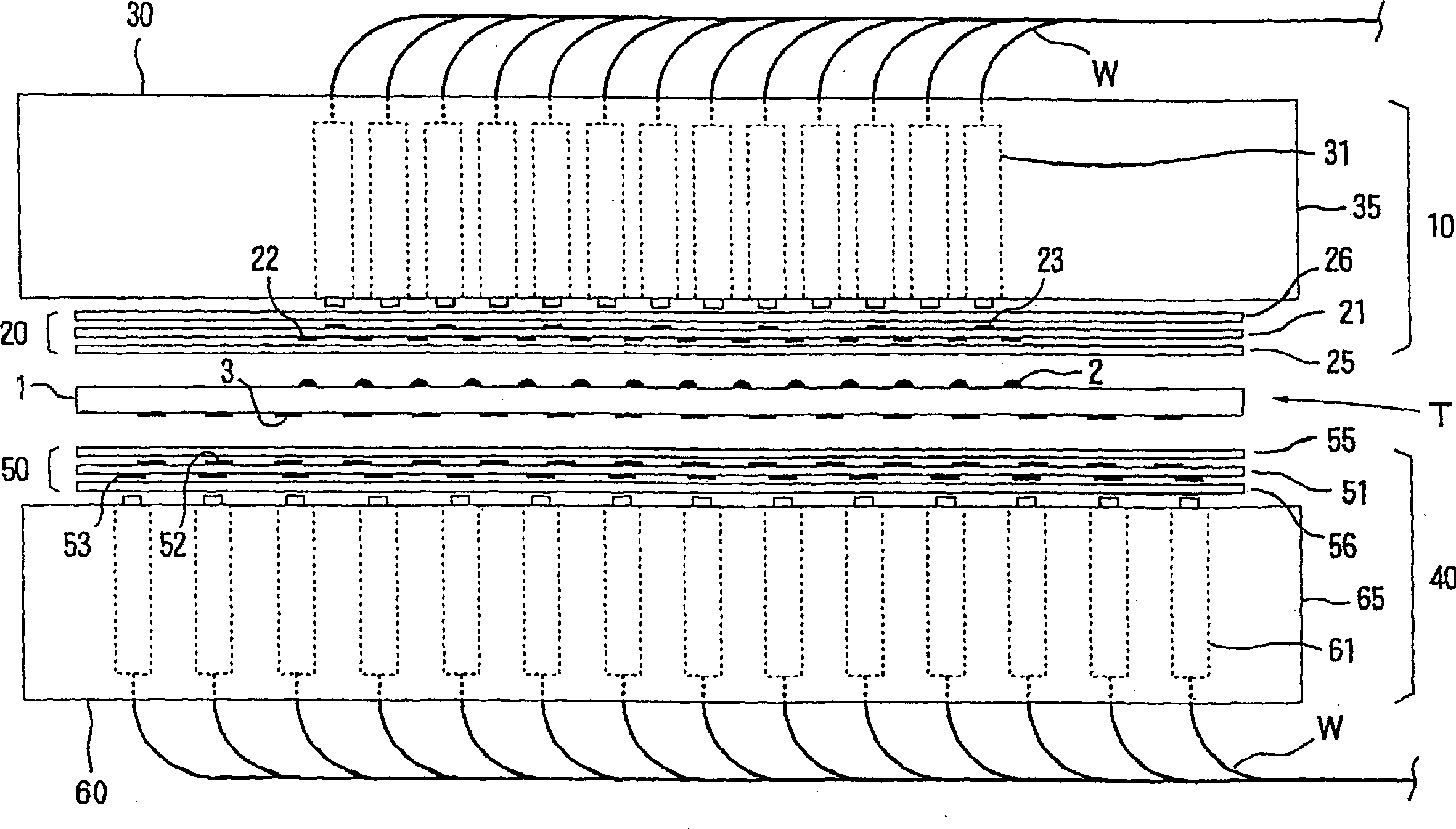
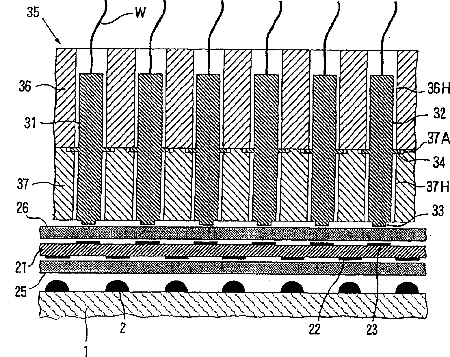
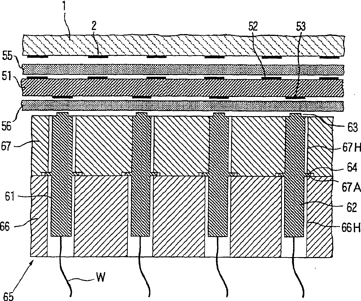
[0233] The circuit board inspection device described below is based on Figures 1 to 3 The structure shown was fabricated.

[0234] [upper adapter (20)]

[0235] The base material of the wiring board (21) is glass fiber reinforced epoxy resin with a thickness of 200 μm, which has 596 circular connecting electrodes (22) and 596 circular terminal electrodes (23), and the minimum diameter of the connecting electrodes (22) The minimum distance between connecting electrodes (22) is 200 μm, the minimum diameter of terminal electrodes (23) is 100 μm, and the minimum distance between terminal electrodes (33) is 200 μm. The terminal electrodes (23) are arranged so that when the wiring board (21) is viewed through the thickness direction, one terminal electrode (23) is located at the center of the specific electrode region (R1), and the terminal electrodes (23) are arranged so as not to cover the connecting electrodes (22) (see Figure 5).

[0236] The first anisotropic conductive ela...

example 2

[0267] The circuit board inspection device described below is based on Figures 8 to 10 The structure shown was fabricated.

[0268] [upper adapter (20)]

[0269] The base material of the wiring board (21) is glass fiber reinforced epoxy resin with a thickness of 200 μm. It has 596 pairs of rectangular connection electrodes (22c), which are respectively composed of a connection electrode (22a) for power supply and a connection electrode (22a) for voltage measurement. Consisting of connecting electrodes (22b), and 1192 circular terminal electrodes (23), the minimum size of connecting electrodes (22a) for power supply and connecting electrodes (22b) for voltage measurement is 30 μm*60 μm, for power supply The gap between the connection electrode (22a) and the connection electrode (22b) for voltage measurement is 30 μm, the minimum distance between the connection electrode pair (22c) is 200 μm, and the diameter of the terminal electrode (23) is 60 μm. The terminal electrodes (2...


PUM


Abstract

A circuit board inspection device is used for inspecting a circuit board where a plurality of electrodes to be inspected are arranged in a gridiron shape. The circuit board inspection device includes: an adapter having a connection wiring plate on surface of which a plurality of connection electrodes are formed so as to correspond to the electrodes to be inspected and an anisotropic conductive elastomer sheet arranged on the surface of the connection wiring plate; and a pressing pin mechanism having a plenty of pressing pins arranged at the rear side of the connection wiring plate. The pressing pins are arranged in such a manner that at least one pressing pin is contained in a rectangular area defined by connecting the center points of four adjacent connection electrodes.

Description

technical field [0001] The present invention relates to a circuit board inspection apparatus and inspection method for inspecting electrical characteristics of circuit boards for manufacturing or mounting electronic components such as integrated circuit devices, and a wiring board which can be suitably used in the circuit board inspection apparatus. Background technique [0002] For circuit boards that manufacture or install electronic components, such as packaging large-scale integrated circuits such as BGA and CSP, MCM, and other integrated circuit equipment, the electrical characteristics of the circuit board must be inspected before assembling or installing electronic components or similar devices. The purpose is to confirm The wiring of the circuit board has the desired performance. [0003] Heretofore known inspection devices for inspecting electrical characteristics of circuit boards include an inspection electrode device in which a large number of inspection electrod...

Claims


Application Information

Patent Timeline
Patent Type & Authority Applications(China)
IPC IPC(8): G01R1/06G01R31/02G01R31/28H05K3/00
CPCG01R31/2808G01R31/28
Inventor 木村浩下田杉郎
Owner ISC CO LTD
Learn More