
Method and device for fire detection and location

A technology for fire and suction devices, which is applied to measurement devices, fire alarms, and fire alarms that rely on smoke/gas action, etc., can solve the problems of complex wiring of auxiliary detectors and high cost of fire identification devices, and achieve The effect of low operating costs and lower construction costs

Inactive Publication Date: 2006-11-15
WAGNER GROUP
View PDF4 Cites 15 Cited by
  • Summary
  • Abstract
  • Description
  • Claims
  • Application Information

AI Technical Summary

Problems solved by technology

The disadvantage of this prior art device is that the cost of the fire identification device is relatively high due to the arrangement of multiple auxiliary detectors, and in addition, the auxiliary detectors require complicated wiring when installing the device

Method used


Image

  • Method and device for fire detection and location
  • Method and device for fire detection and location

Examples


Embodiment Construction

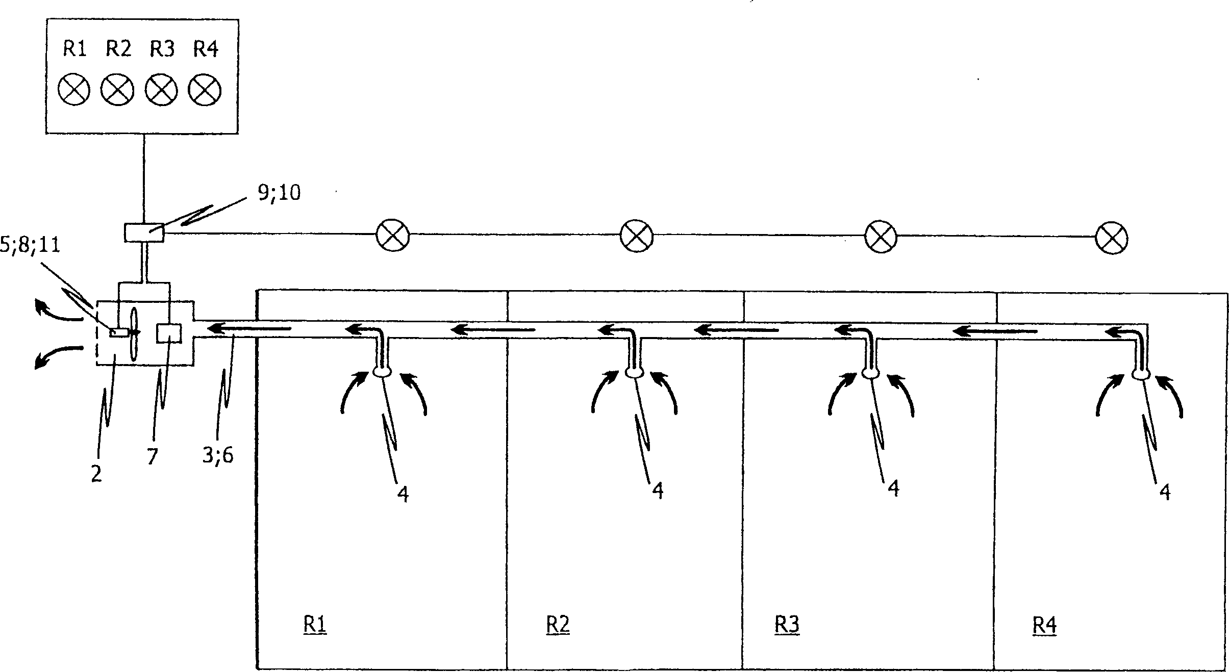
[0054] figure 1 A schematic diagram of a preferred embodiment of the device according to the invention is shown for identifying a fire from a plurality of monitored rooms R1 , R2 , . . . figure 1 The device according to the invention shown relates to a centrally arranged, aspirating fire detection device, which enables the exact localization of a fire. In the embodiment shown, the device is used to monitor 4 separate rooms R1, R2, R3, R4. From each monitored room R1 , . . . , R4 , air samples 6 representing the air of each monitored room R1 , . For this purpose, a suction device 5 in the shape of a blower is provided at the end of the suction pipe system 3 . The air sample 6 sucked by the suction device 5 via the common suction pipe system 3 is sent to a detector or detectors 7 for the identification of one or more fire characteristic values. It is conceivable here that the suction device 5 can be arranged together with the detector 7 in a common housing 2 .

[0055] The d...


PUM


Abstract

The invention relates to a method and a device for identifying and localising a source of fire in at least one monitored region (R1,...,Rn), using a suction pipe system (3) connecting the plurality of monitored regions (R1,...,Rn) and communicating with each individual monitored region (R1,...,Rn) by means of at least one suction opening (4) respectively, a suction device (5) for extracting the air samples (6) respectively representing the ambient air of the individual monitored regions (R1,...,Rn) from the individual monitored regions (R1,...,Rn,) by means of the suction pipe system (3) and the suction openings (4), and a sensor (7) for detecting at least one fire parameter in the air samples (6) extracted by means of the suction pipe system (3). According to the invention, a blowing device (8) is provided for blowing out the air samples (6) sucked into the suction pipe system (3) if the sensor (7) detects at least one fire parameter in the extracted air samples (6). The fire is localised by means of the transit time measurement of a re-extracted air sample containing a fire parameter.

Description

technical field [0001] The present invention relates to a method for identifying and locating fires and / or outbreaks of fire in one or more monitored rooms, and a device for carrying out the method. [0002] The starting point is a fire detection device with a detector for detecting characteristic values ​​of a fire, to which a representative volumetric fraction of the air in a room or appliance is sent via a suction pipe system using a suction device, such as a suction fan detector. [0003] The so-called fire characteristic value here refers to the physical value, which can be measured around the place where the fire occurs, such as ambient temperature, solids, or liquids, or gas components in the surrounding air (generating smoke particles or smoke particles, either form vapor or combustion gases), or ambient radiation. Background technique [0004] The various methods and fire detection devices are known for the detection of fires in advance in the first generation sta...

Claims


Application Information

Patent Timeline
IPC IPC(8): G08B17/00G01N1/26G08B29/26
CPCG01N1/26G08B17/10G08B29/26G08B17/00G08B29/00
Inventor 克劳斯-彼德·来耶克安德列亚思·西门子
Owner WAGNER GROUP
Learn More