Cutting-off device for part machining

A cutting device and parts processing technology, applied in the field of parts processing, can solve the problems of poor product standardization, low production efficiency, large risk factor, etc., and achieve the effects of low production cost, high cutting efficiency and reduced production cost.

Inactive Publication Date: 2018-09-04
江苏世丰企业管理咨询有限公司
View PDF6 Cites 5 Cited by
  • Summary
  • Abstract
  • Description
  • Claims
  • Application Information

AI Technical Summary

Problems solved by technology

In the production and processing of mechanical parts, rust-resistant and high-strength steel bars are usually used as raw materials. Therefore, the steel bars need to be cut at the initial stage of processing parts. The traditional method

Method used


Image

  • Cutting-off device for part machining

Examples


Example Embodiment

[0012] The following is a further detailed description through specific implementations:

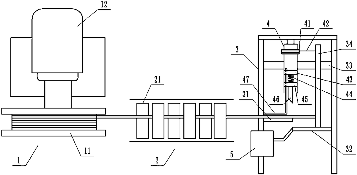
[0013] The reference signs in the drawings of the specification include: unwinding mechanism 1, material tray 11, first motor 12, straightening mechanism 2, straightening roller 21, fixed frame 3, upper conveying section 31, lower conveying section 32, slide rail 33. Stop rod 34, main shaft 4, fixed block 41, pull line 42, first stud 43, flexible spring 44, second stud 45, cutting knife 46, limit rod 47, processing device 5.

[0014] The embodiment is basically as attached figure 1 Shown: The cutting device for parts processing includes a feeding mechanism 1, a straightening mechanism 2, a fixing frame 3, and a cutting mechanism in turn. The feeding mechanism 1 includes a first motor 12 and a tray 11 for supporting the steel coil. The disc 11 is fixedly connected to the output shaft of the first motor 12. The straightening mechanism 2 includes a plurality of pairs of straightening rollers 21...


PUM


Abstract

The invention relates to the technical field of part machining, and particularly discloses a cutting-off device for part machining. The cutting-off device for part machining comprises a fixed frame provided with a conveying rod and a cutting mechanism located above the conveying rod. The cutting mechanism comprises a spindle and a cutting-off knife. The lower portion of the spindle is hollow, andthe lower end of the spindle is open. Internal threads are arranged in the hollow interior of the spindle. A first stud and a second stud are connected into the hollow lower portion of the spindle ina threaded mode from top to bottom. An elastic rope is arranged between the first stud and the second stud. The lower end of the second stud is fixedly connected with the cutting-off knife. A slidingrail is arranged on the fixed frame. A stop lever is slidably connected to the sliding rail. A traction rope and a torsion spring are wound on the spindle and fixedly connected with the stop lever. The conveying rod is divided into an upper conveying section and a lower conveying section from a lower vertical position corresponding to the cutting-off knife, and the stop lever extends to the lowerconveying section. According to the cutting-off device, steel bars for manufacturing parts can be automatically cut by a fixed length and can be automatically discharged, and the cutting process is continuously conducted online, so that the cutting efficiency is high; and energy consumption is low, and the production cost can be effectively reduced.

Description

technical field [0001] The invention relates to the technical field of part processing, in particular to a cutting device for part processing. Background technique [0002] Mechanical parts are important basic elements that make up machinery and machines, including bolts, rivets, nuts, gears and other components. In the production and processing of mechanical parts, rust-resistant and high-strength steel bars are usually used as raw materials. Therefore, the steel bars need to be cut at the initial stage of processing parts. The traditional method of cutting steel bars is generally manual fixed-length cutting, and manual fixed-length cutting exists It has disadvantages such as high operating cost, high risk factor, low production efficiency, and poor standardization of manufactured products. Contents of the invention [0003] The purpose of the present invention is to provide a cutting device for parts processing, which can automatically cut the steel bars for making part...

Claims


Application Information

Patent Timeline
IPC IPC(8): B21F11/00B21F23/00
CPCB21F11/00B21F23/00
Inventor 李志华
Owner 江苏世丰企业管理咨询有限公司
Why Eureka
Try Eureka