High rigid exhibition table fastener for rapid connection of members

A fast connection, high rigidity technology, applied in the connection of rods, furniture connections, connecting components, etc., can solve problems such as insufficient support rigidity, and achieve the effect of correct positioning

Active Publication Date: 2006-11-22
金元安
View PDF1 Cites 13 Cited by
  • Summary
  • Abstract
  • Description
  • Claims
  • Application Information

AI Technical Summary

Problems solved by technology

[0003] The object of the present invention is to address the above-mentioned defects and propose a high-rigidity component connection lock,

Method used


Image

  • High rigid exhibition table fastener for rapid connection of members
  • High rigid exhibition table fastener for rapid connection of members

Examples


Embodiment Construction

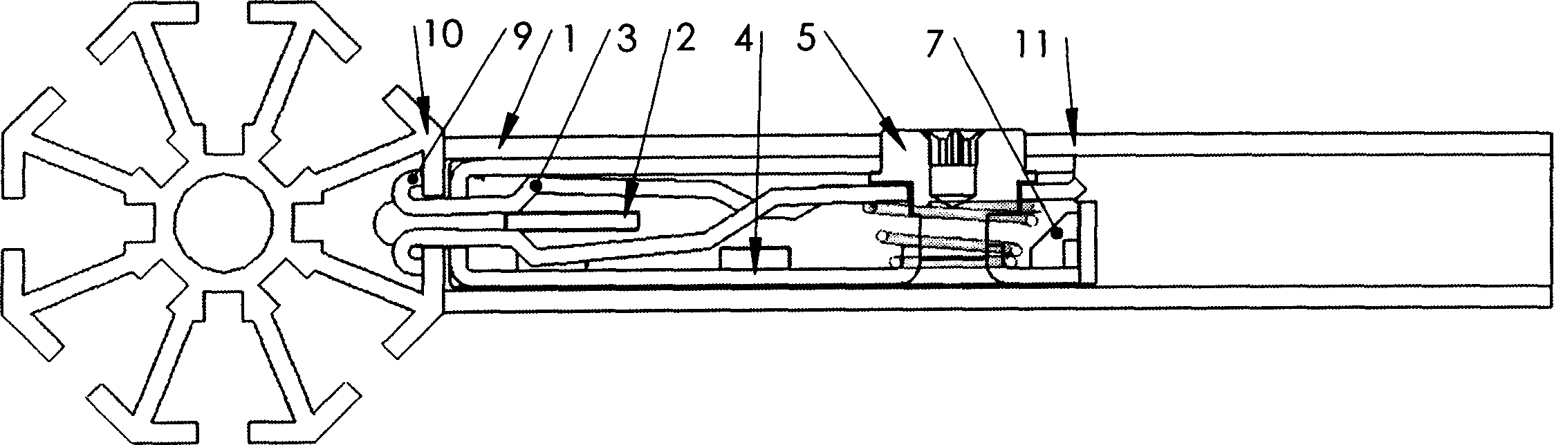
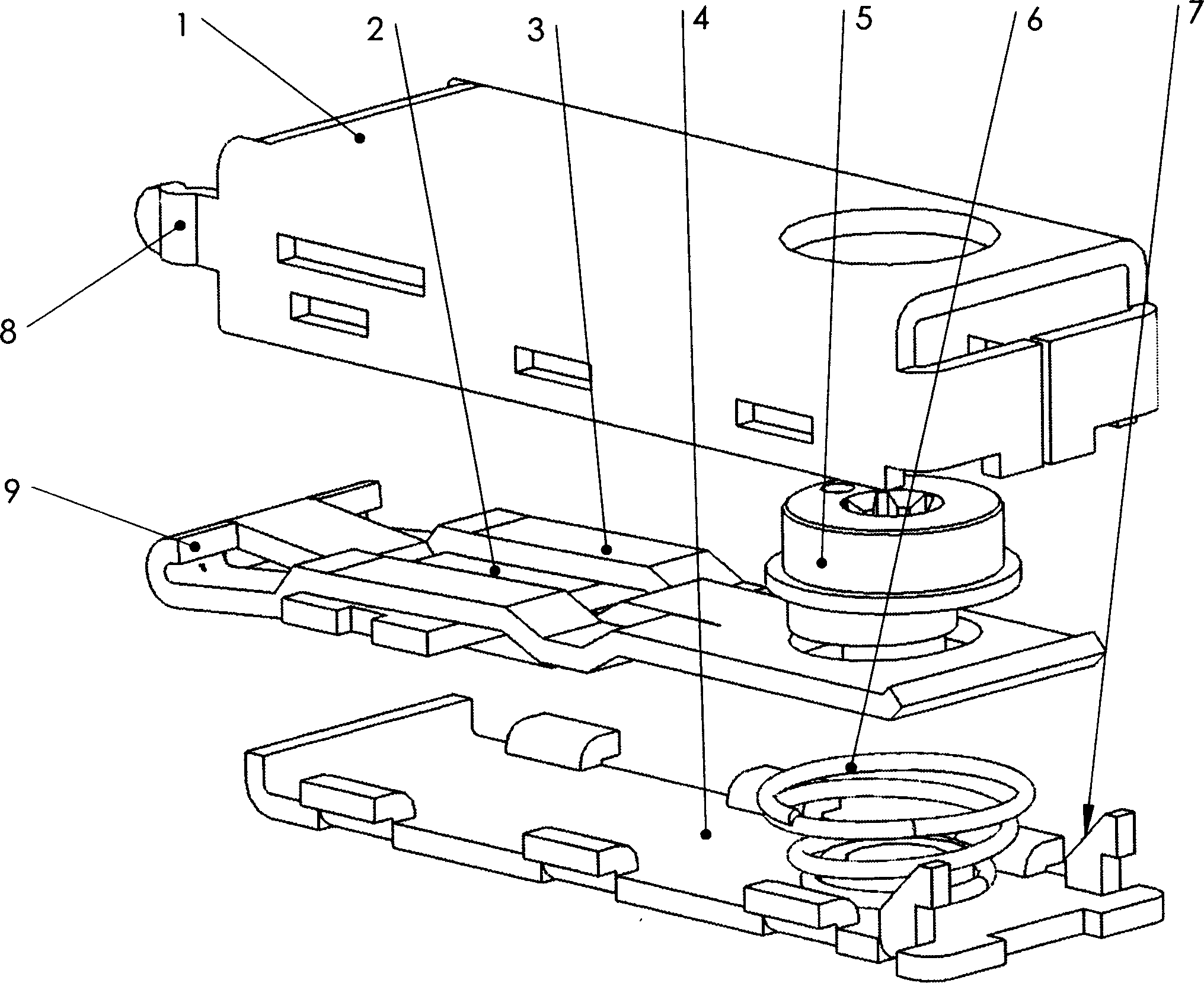
[0011] Referring to the accompanying drawings, its structure is composed of a shell 1, an inner support plate 2, a reed 3, a bottom plate 4, a spring 6 and an eccentric wheel 5; the shell 1 and the bottom plate 4 form a rectangular space, and the corresponding positions of the shell 1 and the bottom plate 4 There is a circular hole, and the eccentric wheel 5 is installed in this circular hole; the front end of the reed 3 is divided into three pieces, and the lock hooks used as the bayonet are respectively provided, and the lock hooks on both sides and the middle lock hook are opposite to each other. Curved, the rear part is a whole and has a non-circular hole, and the end has a bevel. The reed 3 is installed between the boss of the eccentric wheel 5 and the spring 6, and the inner support plate 2 is installed in the middle of the three separated front ends of the reed 3, and both sides are riveted on the shell. The non-circular hole on the reed 3 matches with the eccentric whe...


PUM


Abstract

The invention discloses a high-rigidity lock for quick connection. Wherein, it is formed by a frame, an inner support plate, a spring plate, a bottom plate, an eccentric wheel, and a spring; the frame and the bottom plate form one rectangle space with a round hole; said round hole contains one eccentric wheel; the front of spring plate is mounted with lock hooks that reversed bended; it is characterized in that: the inner support plate is at the middle of spring plate, while its two sides are supported by frame; the front of lock has one taper guide block. Compared with present technique, in said invention, the lock hook is supported on the inner support plate; the inner support plate is riveted on the frame; two sides of inner support plate bear symmetry forces, to support the lock hook and confirm enough rigidity; the guide block is taper, therefore, the lock hook can be easily inserted into the locked element.

Description

technical field [0001] The invention relates to a high-rigidity exhibition booth lock used for quick connection of structural parts. It belongs to the technical field of connectors. Background technique [0002] Prior art, such as ZL00221901.8, its structure is composed of shell, bottom plate, eccentric wheel, spring and reed, wherein the shell is made into a hollow rectangle, the lower part of the shell has a circular opening, and the eccentric wheel is installed in the shell, The reed is between the boss of the eccentric wheel and the bottom plate. The front end of the reed is provided with three locking hooks as bayonets. The middle locking hook and the two locking hooks on both sides are opposite to each other, and the eccentric wheel drives the reed to move forward and backward. The diagonal braces of the shell and the bottom plate correspond to the slopes of the locking hooks on the reed respectively. The diagonal bracing of the shell is provided with reinforcing ri...

Claims


Application Information

Patent Timeline
IPC IPC(8): F16B12/00A47F7/00F16B7/00F16B12/54
Inventor 金元安
Owner 金元安
Why Eureka
Try Eureka