
Method for monitoring torsional vibration damper

A technology of torsional vibration and shock absorber, applied in the direction of applying repetitive force/pulse force to test material strength, instrument, torque measurement, etc., can solve problems such as measuring torque load

Active Publication Date: 2006-11-22
盖斯林格集团有限公司
View PDF0 Cites 14 Cited by
  • Summary
  • Abstract
  • Description
  • Claims
  • Application Information

AI Technical Summary

Problems solved by technology

Based on the detection of the joint part of the torsional rotation damper and the digital rotation steps of the vibrating rotating body, the measurement of the torsion angle can be easily carried out, but the comparison between the measured torsion angle and the predetermined limit value does not allow Torsional vibration dampers are monitored with the accuracy required for many intended uses, since such monitoring requires knowledge of specific torsional rigidity and torsional damping
It has been proposed to calculate the torsional rigidity of a torsional vibration damper by measuring the transmitted torque and the relative torsion angle between the connecting part and the vibrating rotating body to which it is connected in a rotationally elastic manner, but it is difficult This torque load is measured by the strain gauge in synchronization with the digital rotation steps
Furthermore, the use of strain gauges while taking into account the required signal transmission is only possible at great expense and, moreover, only in a restricted manner in torsional vibration dampers

Method used


Image

  • Method for monitoring torsional vibration damper
  • Method for monitoring torsional vibration damper

Examples


Embodiment Construction

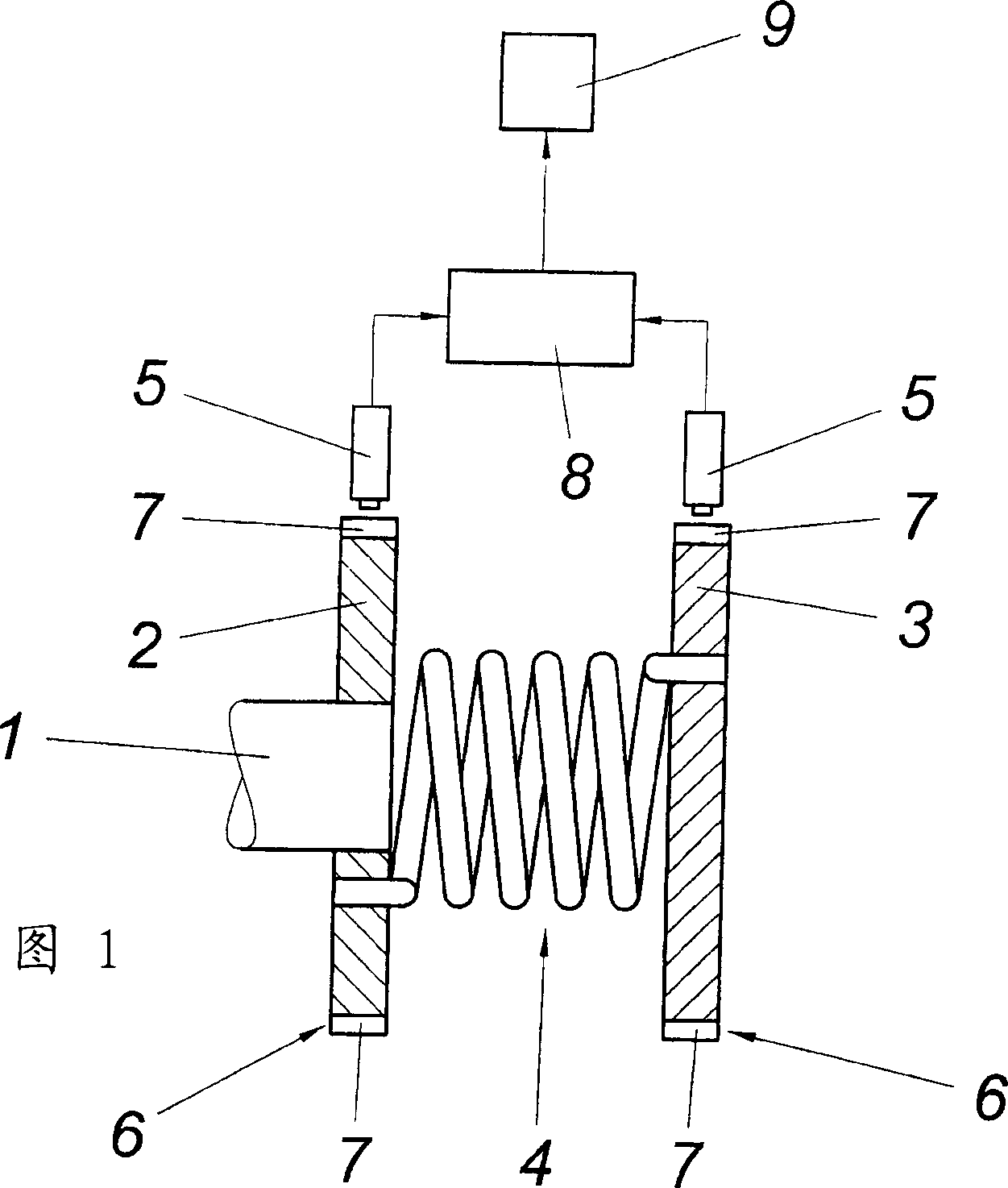
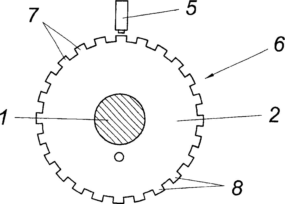
[0010] As can be seen in FIG. 1 , the torsional vibration damper basically has a connection part 2 connected to the crankshaft 1 of the internal combustion engine, and, for example, a seismic rotational mass 3 which is connected to the connection in a rotationally elastic manner. Part 2. This rotationally elastic connection 4 is shown in the form of a torsion spring, but can be constructed in a different manner, since the type of rotationally elastic connection 4 of the connection part 2 to the vibrating rotor 3 is not important here, but is based on torsional rigidity and torsional damping. The functional reliability of the torsional vibration damper is monitored, which is largely independent of the constructional embodiment of the particular torsional vibration damper. Of course, these characteristic values ​​of the torsional vibration damper can also be continuously monitored during use of the torsional vibration damper in order to monitor its functional reliability.

[00...


PUM


Abstract

The invention discloses a method for monitoring a torsional vibration damper. The torsional vibration damper has a connecting part (2) connectable to a shaft and a vibration rotating body (3) connected to the connecting part (2) in a rotationally elastic manner. The connecting part (2) and the vibration rotating body (3) ) is digitally measured and converted in the computing station to output characteristic values. In order to ensure favorable monitoring conditions, the invention proposes to determine the relative twisting angle between the two parts (2, 3) and furthermore determine the vibration rotation by simultaneously measuring the angle of rotation of the connecting part (2) and the vibration rotating body (3). The rotational angular acceleration of the body (3), taking into account any changes in the angular velocity of the connecting part (2), and with the help of a vibrating rotating body (3) by constructing a predetermined mass moment of inertia the torsional stiffness and torsional damping are calculated and displayed as characteristic values .

Description

technical field [0001] The invention relates to a method for monitoring a torsional vibration damper having a connection part connectable to a shaft and a vibration rotating body connected to the connection part in a rotationally elastic manner, the connection part and the vibration The angle of rotation of the rotating body is digitally measured and converted in a computing station to output characteristic values. Background technique [0002] In drivetrains in which torsional vibrations occur, for example in the case of drivetrains with internal combustion engines, torsional vibration dampers are used which limit torsional vibrations to permissible magnitudes and thus reduce the torsional vibrations resulting from torsional alternating stress The strain of the driving part is limited to the allowable value. The unimpaired function of the damper is thus of considerable importance in such drive trains, so that at least in certain cases the torsional vibration damper is cont...

Claims


Application Information

Patent Timeline
Patent Type & Authority Applications(China)
IPC IPC(8): G01M13/02G01M15/04
CPCG01L3/109G01N3/34G01N2203/0021G01N2203/0288G01N2203/0676
Inventor 费利克斯·马蒂内克
Owner 盖斯林格集团有限公司
Learn More