Fresnel lens, transmission screen, and rear projection-type display device using the lens

A Fresnel lens and display device technology, applied to projectors, lenses, and projection devices with built-in screens/external screens, etc., can solve the problems of increased thickness of projection display devices, prevent stray light, and avoid additional components or working hours

Inactive Publication Date: 2006-11-22
TOPPAN PRINTING CO LTD
View PDF10 Cites 3 Cited by
  • Summary
  • Abstract
  • Description
  • Claims
  • Application Information

AI Technical Summary

Problems solved by technology

In particular, it also depends on the position of the projector, but the main reflector needs to have a deflection angle, and the maximum can reach about 45 degrees. Therefore, the deflected space directly results in an increase in the thickness of the rear projection display device.

Method used


Image

  • Fresnel lens, transmission screen, and rear projection-type display device using the lens
  • Fresnel lens, transmission screen, and rear projection-type display device using the lens
  • Fresnel lens, transmission screen, and rear projection-type display device using the lens

Examples


no. 1 approach

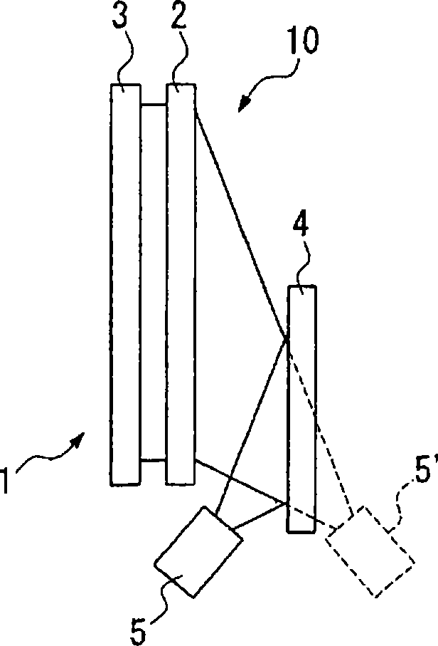
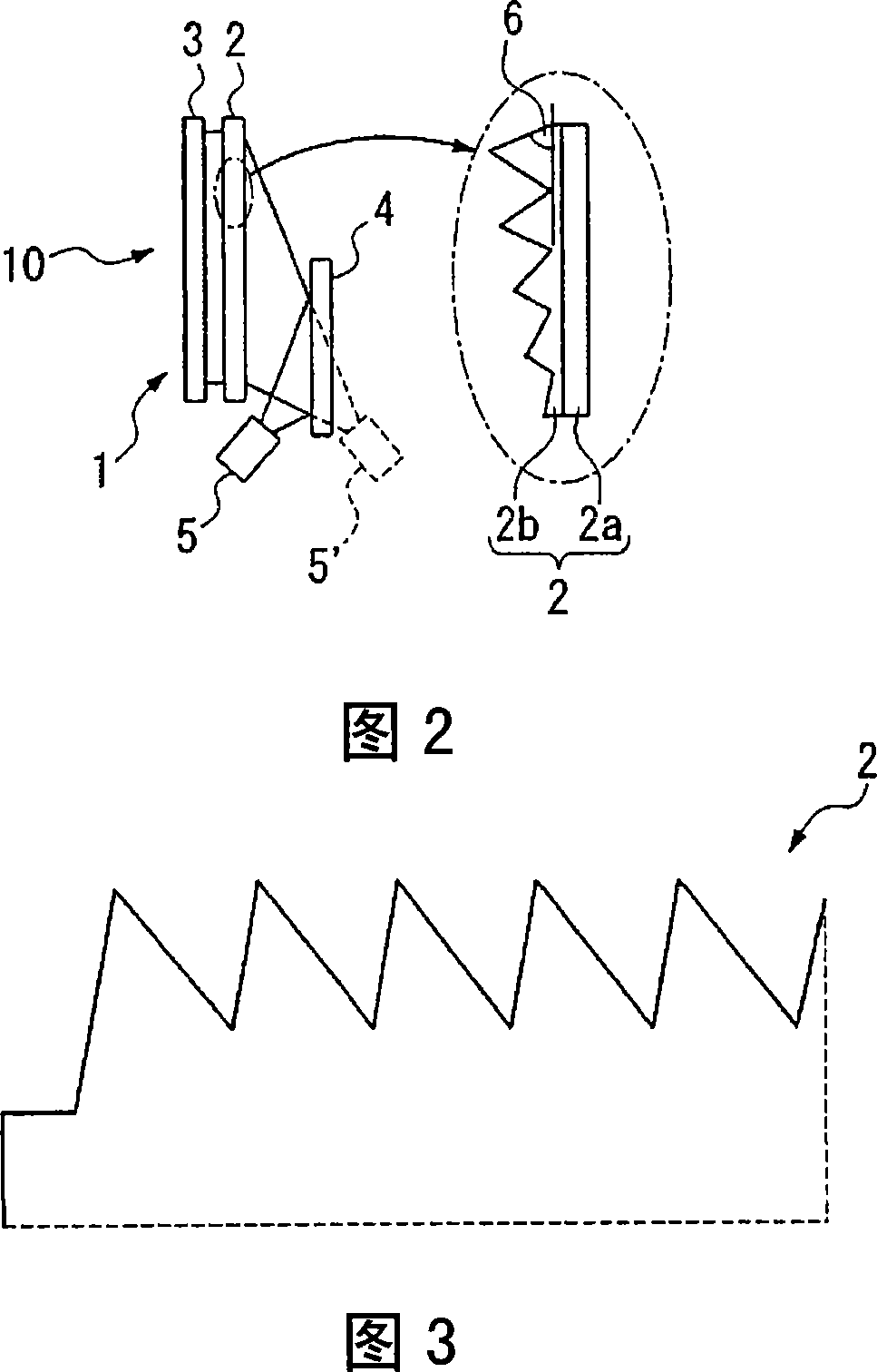
[0070] exist figure 1 In , a configuration example of a rear projection display device 10 using the transmissive screen 1 of the present invention is shown. The rear projection display device 10 has: a transmissive screen 1, whose optical system is mainly composed of a Fresnel lens sheet 2 and a light diffusion plate 3; a projector 5, which projects images to the transmissive screen 1; a plane mirror 4, It is arranged at about the middle position between the transmissive screen 1 and the projector 5. The rear projection display device 10 can make the image light projected from the projector 5 pass through the plane reflector 4 (main reflector) to the transmissive screen 1. reflected and projected on a transmissive screen so that an observer on the opposite side observes the image.

[0071] The projector 5 is configured to project an image obliquely with respect to the transmissive screen 1 . If the projector 5 is arranged in this way, the image projected on the transmissive ...

no. 2 approach

[0097] FIG. 5 shows another configuration example of a rear projection display device 20 using the transmissive screen 1 of the present invention. The rear projection display device 10 is composed of the following objects, and is a schematic diagram showing the situation of setting with an inclination angle, namely: a transmissive screen 11, and its optical system is mainly composed of a Fresnel lens sheet 12 and a light diffusion plate 13 Projector 15, which projects an image to the transmissive screen 11; Plane reflector 14, which is disposed approximately in the middle between the transmissive screen 11 and the projector 15, showing a schematic view of the situation where the inclination angle is set on the planar reflector 14 .

[0098] Here, the projector 15' and the light shown by the dotted line in the figure represent the arrangement when directly projecting an image onto the transmissive screen 11 without the plane mirror 14.

[0099] exist figure 1 In the case wher...


PUM


Abstract

A rear projection-type display device has a Fresnel lens sheet where a lens pattern having a Fresnel surface as a light ray transmissive surface and a rise surface as a non-light ray transmissive surface are concentrically formed and where the optical axis, the center of the lens pattern, of a Fresnel lens is positioned outside the Fresnel lens sheet; a transmission screen having a light diffusion plate; a projector capable of projecting an image on the transmission screen; and a reflection mirror provided between the projector and the transmission screen. The reflection mirror is installed at a substantially middle position between the projector and the transmission screen.

Description

technical field [0001] The invention relates to a Fresnel lens sheet used in a transmissive screen, a transmissive screen, and a rear projection display device using them. [0002] this application claims priority to Japanese Patent Application No. 2003-353272 for which it applied on October 14, 2003, and uses the content here. Background technique [0003] Historically, the rear projection screen has been widely used as a kind of projection screen. A television using this rear projection screen is constructed as follows. Generally, image light projected from a projector equipped with a light source, an image display body, and a projection lens passes through a Fresnel lens sheet having a Fresnel lens and a lenticular lens having a lenticular lens. piece, communicated to the observer. [0004] The projection TV screen generally pursues the optical function of diffused widely in the horizontal direction and diffused narrowly in the vertical direction than in the horizontal ...

Claims


Application Information

Patent Timeline
Patent Type & Authority Applications(China)
IPC IPC(8): G03B21/62G02B3/08G02B5/02G03B21/00G03B21/10G03B21/625H04N5/74
CPCG02B3/08G03B21/625H04N9/3141
Inventor 海老名一义阿部崇高桥进友野孝夫
Owner TOPPAN PRINTING CO LTD
Why Eureka
Try Eureka