Tooth electric time gate sensor

A sensor, electrical technology, applied in the field of displacement sensors, can solve the problems of unsuitable use, high product cost, easy deformation and damage, etc., to achieve the effect of simple winding, low cost, and uniform coil distribution

Inactive Publication Date: 2006-11-29
CHONGQING UNIV OF TECH
View PDF0 Cites 10 Cited by
  • Summary
  • Abstract
  • Description
  • Claims
  • Application Information

AI Technical Summary

Problems solved by technology

They have the advantage of high precision, the disadvantage of being too expensive and not suitable for use in harsh environments
The reason is that the measurement accuracy of the above-mentioned sensor depends on the manufacturing accuracy of its own reference parts. The precise manufacturing process leads to high product costs, and the precise structure makes it particularly delicate and easy to deform and damage.

Method used


Image

  • Tooth electric time gate sensor
  • Tooth electric time gate sensor
  • Tooth electric time gate sensor

Examples


Embodiment Construction

[0020] For convenience, first describe the structure of the present invention by taking angular displacement as an example:

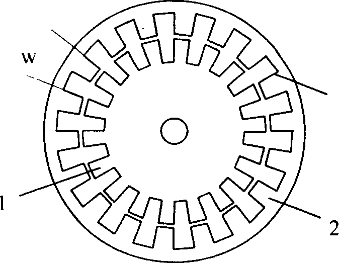
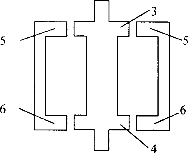
[0021] First machine the toothed coil skeleton such as Figure 1A and Figure 1B As shown, the inside is the rotor 1, and the outside is the stator 2. There are two sets of slotted teeth 3, 4 and 5, 6 parallel up and down on the outer circumference of the rotor and the stator. The number of teeth is not limited, generally an even number, and is a double gear . Among them, the two sets of slotted teeth 5 and 6 on the stator are designed to be staggered by half teeth along the circumference to form orthogonal, and the two sets of slotted teeth on the rotor are not separated. Figure 1A W in is the tooth pitch.

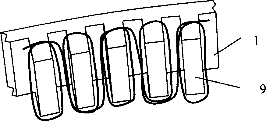
[0022] Then on each tooth-shaped skeleton, take two adjacent teeth as a group and wind the coil n turns in the forward direction and the reverse direction respectively, forming the following shape: figure 2 Groups of coils in series distributed...


PUM


Abstract

The invention advances a new tooth electro time-grating displacement sensor able to make both dynamic and static measurement, making two groups of teeth on both stator/scale and rotor/slide, selecting two groups of teeth on the stator/scale or rotor/slide and staggering by half tooth to form orthogonal, not staggering the other two groups of teeth, forward and backward winding coils on the stator/scale and rotor/slide at regular tooth intervals, using two groups of coils as excitation coils and exciting by two orthogonal simple harmonic waves so as to obtain standing wave responses in the other two groups of coils as standing response coils, superposing the two standing waves and obtaining electric travelling wave whose phase shift directly reflects angular or linear displacement. And its stator/scale and rotor/slide framework can be machined by any common- precision machining device to assure uniform coil distribution, and it can replace any present static and dynamic measuring means to implement high-precision measurement.

Description

technical field [0001] The invention belongs to displacement sensor technology. Background technique [0002] Among the existing static and dynamic displacement sensors, represented by magnetic gratings, gratings, and inductive synchros, they have been widely used for many years. They have the advantage of high precision and the disadvantage of being too expensive and not suitable for use in harsh environments. The reason is that the measurement accuracy of the above-mentioned sensor depends on the manufacturing accuracy of its own reference part. The precise manufacturing process leads to high product cost, and the precise structure makes it particularly delicate and easy to deform and damage. Contents of the invention [0003] The object of the present invention is to solve the above problems, and propose a new tooth electric time grid displacement sensor (tooth electric grid for short) that can take into account both dynamic and static measurements at the same time. A...

Claims


Application Information

Patent Timeline
Patent Type & Authority Applications(China)
IPC IPC(8): G01D5/12G01B7/02
Inventor 彭东林和子康刘小康陈锡侯杨伟张兴红朱革王先全
Owner CHONGQING UNIV OF TECH
Why Eureka
Try Eureka