Heat shrinking positioning method and heat shrinking positioning plate for super-thin wire conduit

A technology of ultra-thin wires and positioning methods, applied in the direction of cable joints, cable installation devices, electrical components, etc., can solve the problems of easy errors in manual operation, and achieve the effect of simple operation and high efficiency

Inactive Publication Date: 2006-11-29
张志辉 +1
View PDF0 Cites 5 Cited by
  • Summary
  • Abstract
  • Description
  • Claims
  • Application Information

AI Technical Summary

Problems solved by technology

If the positioning of the sleeve is inaccurate, it will not be able to snap into the position of the corresponding main box, but manual operation is prone to errors. If it is necessary to process such wire groups with heat shrinkable positioning sleeves in large quantities, it is impossible

Method used


Image

  • Heat shrinking positioning method and heat shrinking positioning plate for super-thin wire conduit
  • Heat shrinking positioning method and heat shrinking positioning plate for super-thin wire conduit
  • Heat shrinking positioning method and heat shrinking positioning plate for super-thin wire conduit

Examples


Embodiment Construction

[0023] control figure 1 To 3 below for further description:

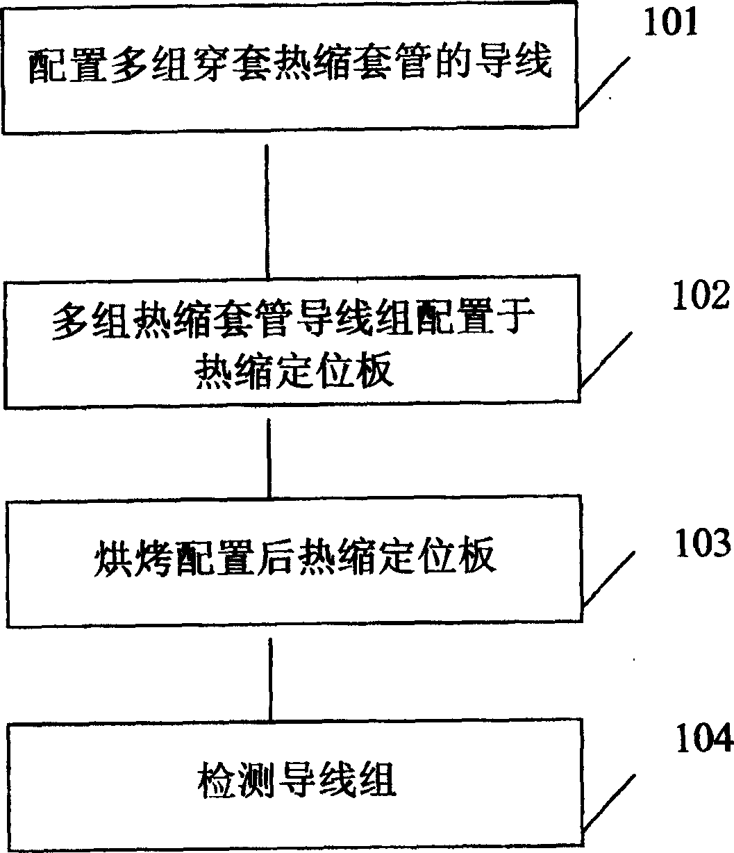
[0024] A heat-shrinkable positioning method for ultra-fine wire sleeves, which is used for heat-shrinking and positioning multiple sets of ultra-fine wire sleeves at the same time, comprising the following steps in sequence:

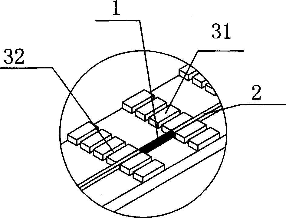
[0025] 1). Put multiple heat-shrinkable sleeves 1 through the wire group 2 formed by one or more wires;

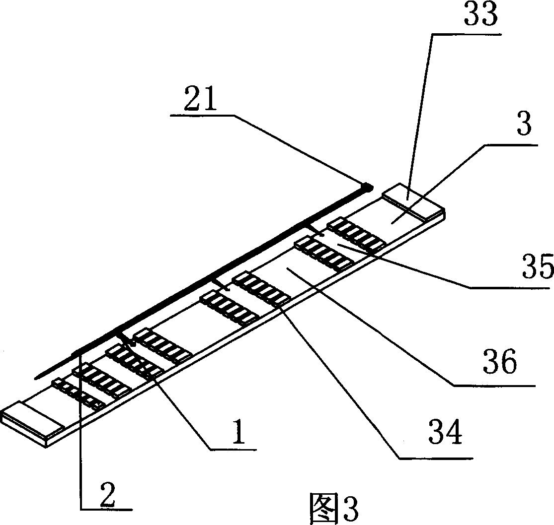
[0026] 2). Place the wire group in the transverse limit groove 32 arranged at intervals by a plurality of casing positioning blocks 31 on the heat-shrinkable positioning plate 3, and connect the flush end 21 of the wire group to the heat-shrinkable positioning plate The stop portion 33 at one end is aligned;

[0027] 3). A plurality of heat-shrinkable sleeves on the wire group are respectively limited in a plurality of longitudinal limiting grooves 35 arranged at intervals by a plurality of block rows 34 on the heat-shrinkable positioning plate, so as to facilitate hot air baking;

[00...


PUM


Abstract

This invention relates to a method for heat shinking location of a super fine lead sleeve including: multiple heat shinking sleeves jacket a lead set composed of one or multiple leads, which is set in a lateral spacing groove of a heat shinking locating board and the flat end of which is aligned with one end of the board, multiple sleeves on the lead set are limited in multiple longitudinal spacing grooves set in space by multiple block arrays, the multiple lead sets are set in different lateral spacing grooves of the board according to the steps to form preset heat shinking locating boards to be baked in a hot air oven orderly based on conveyer belts, the temperature and time of the baking are decided by the material of the sleeves and speed of the belt and the outlook of the sleeves and the located positions are tested.

Description

technical field [0001] The invention relates to a heat-shrinkable positioning method and a special tool for a wire sleeve, in particular to a heat-shrinkable positioning method for an ultra-fine wire sleeve and a heat-shrinkable positioning plate. Background technique [0002] In the prior art, it is common to insert a wire or a wire group formed by a plurality of wires into a heat-shrinkable sleeve after being heat-shrinkable and shaped, and then clip it into the application device, especially in a notebook computer where one or more super The wire group composed of thin wires is shrunk through the heat-shrinkable sleeve and snapped into the corresponding position. Due to the small size of the ultra-fine wire and the computer, it needs to be manually produced. The method is: according to the different positions of the computer mainframe, heat-shrink the sleeves that pass through the sleeve and position them at different positions of the ultra-thin wire group, and then heat ...

Claims


Application Information

Patent Timeline
Patent Type & Authority Applications(China)
IPC IPC(8): H02G1/00H02G3/04H02G15/18H05K7/00
Inventor 张志辉林炯星
Owner 张志辉
Why Eureka
Try Eureka