

Work carrying device of pressing machine
A technology for conveying devices and workpieces, which is applied in the directions of feeding devices, positioning devices, storage devices, etc., can solve the problems of increasing the number of linear motors, increasing manufacturing costs, and insufficient effects, reducing the number, reducing noise, cost reduction effect
- Summary
- Abstract
- Description
- Claims
- Application Information
AI Technical Summary
Problems solved by technology
Method used
Image

Examples
Embodiment approach 1
[0095] The first embodiment of the present invention will be described.
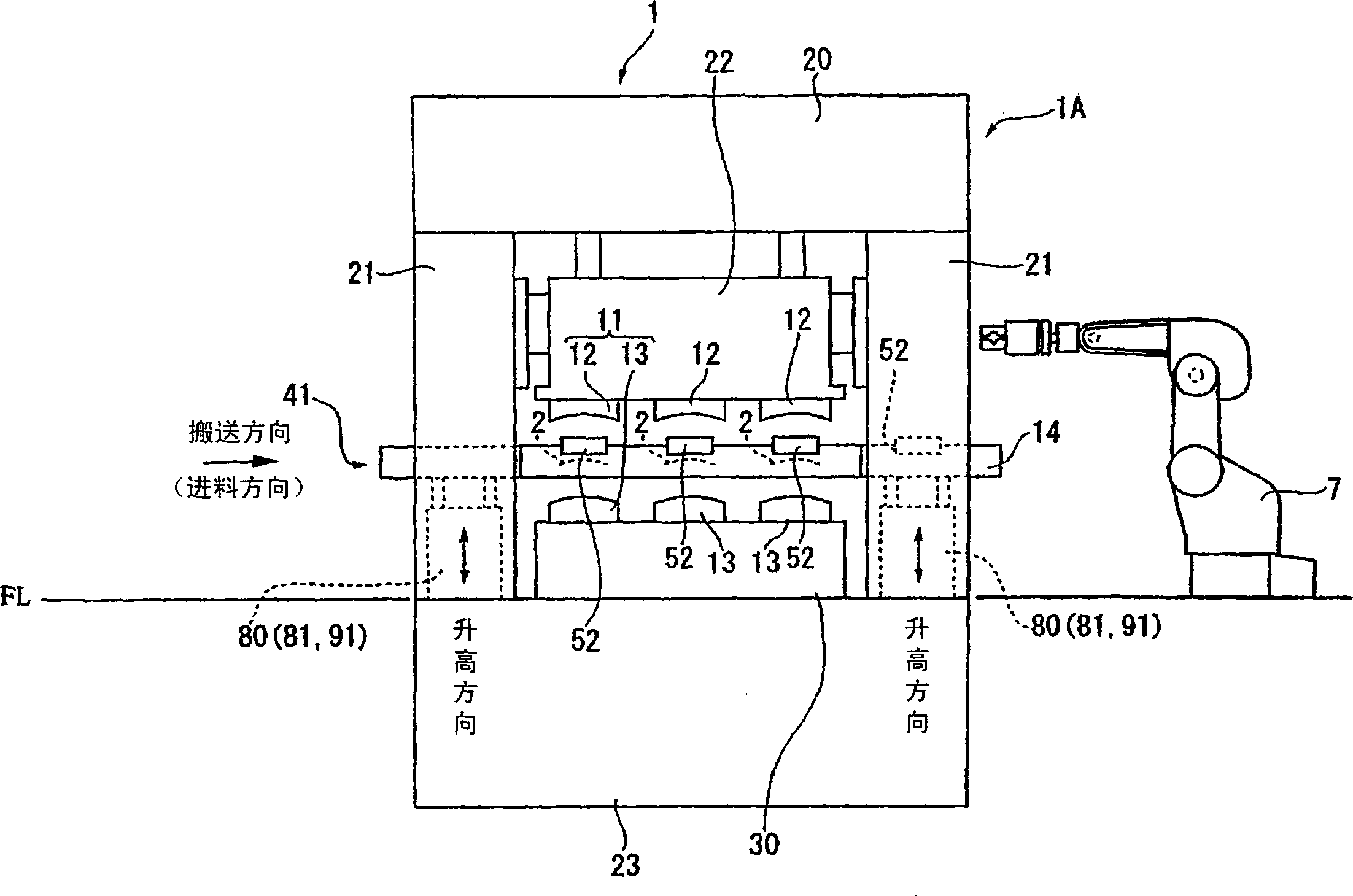
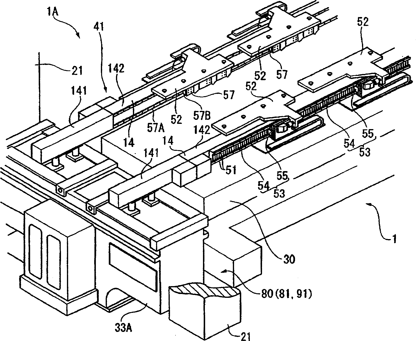
[0096] figure 1 A front view of the continuous automatic press (press machine) 1 according to Embodiment 1 of the present invention is shown in FIG. figure 2 It is a perspective view of a continuous automatic press (work transfer device) 41.
[0097] First, use figure 1 The overall configuration of the continuous automatic press 1 as the first embodiment of the present invention will be described.
[0098] The continuous automatic press 1 consists of a press main body 1A composed of a machine tool 23, a support column 21, a beam 20, and a slider 22, a mold 11 equipped with an upper mold 12 and a lower mold 13, a movable table 30, and a continuous automatic feeder 41 constitute. In addition, a general-purpose robot 7 for carrying out the workpiece is provided on the downstream side of the continuous automatic press 1.
[0099] Under the floor (FL), there is a machine tool 23 that becomes the base of the c...
Embodiment approach 2
[0147] Next, the second embodiment of the present invention will be described. In addition, the same symbols are used for the same parts as those explained in the first embodiment, and the explanation will be omitted. The continuous automatic feeder 41A of the second embodiment uses one linear motor 53A for feeding horizontally installed on the rod 14 to move a plurality of feeding carriers 52 connected to each other for feeding. The mode 1 continuous automatic feeder 41 is different.
[0148] Figure 13 There is shown a perspective view of a continuous automatic feeder 41A according to Embodiment 2 of the present invention. As that Figure 13 As shown, in the second embodiment, a moving member 58 is provided on the fixed rod 141 at one end of the rod 14. The moving member 58 is arranged between the linear motor 57 and the upper surface of the rod 14 so as to move freely in the feeding direction. guide. The feeding drive mechanism of the present invention is constituted by provid...
Embodiment approach 3
[0158] Next, the third embodiment of the present invention will be described. In addition, the same reference numerals are used for the same parts as those described in the first and second embodiments, and the description thereof will be omitted. In the third embodiment, the feed carrier 52 of the first embodiment is driven by a servo motor, and is different from the first embodiment in this point.
[0159] Figure 14 It is a perspective view showing a part of the continuous automatic feeder 41B of the third embodiment. As that Figure 14 As shown, the rod 14AA is the same as in the first embodiment. A pair of rods 14AA are provided in parallel with the workpiece conveying direction. A plurality of feed carriers 52B are provided on a pair of feed rails 51, 51 on the upper surface of the rod 14AA, and are respectively provided. Can be configured separately and mobile. and, Figure 14 Although one feed carrier 52B is shown in, any number can be set as needed.
[0160] The feed car...
PUM
 Abstract
Description
Claims
Application Information