Refrigerator
A refrigerator and outer box technology, applied in refrigerators/freezers, household refrigerators, coolers, etc., can solve the problems of limited refrigeration cycle, complicated refrigerator structure control, and rising costs, so as to suppress complexity and improve refrigeration cycle Efficiency, cooling capacity improvement effect
- Summary
- Abstract
- Description
- Claims
- Application Information
AI Technical Summary
Problems solved by technology
Method used
Image
Examples
Embodiment approach 1
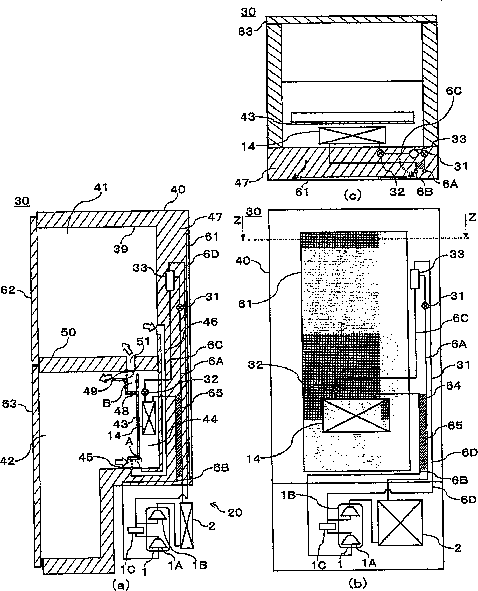
[0033] One embodiment of the present invention will be described in detail based on the drawings. figure 1 It shows the schematic structure diagram of the refrigerator of this embodiment, and the same figure 1 (a) is a side sectional view of the refrigerator 30 of the present embodiment, and figure 1 (b) is the rear view of the same refrigerator 30, the same figure 1 (c) is the same figure 1 (b) Cross-sectional view of line Z-Z.
[0034] Such as figure 1 As shown in (a), the refrigerator 30 has a refrigeration cycle device 20, an outer case 40, an inner case 39, doors 62, 63, and an intermediate partition wall 50, and the inner case 39 is divided by the doors 62, 63 and the intermediate partition wall 50 to form There are refrigerator compartment 41 and freezer compartment 42 .
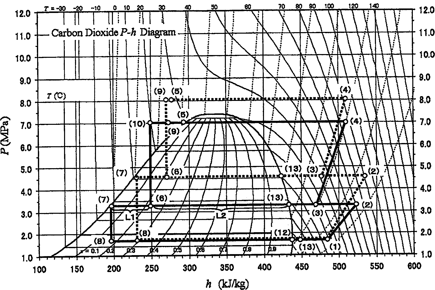
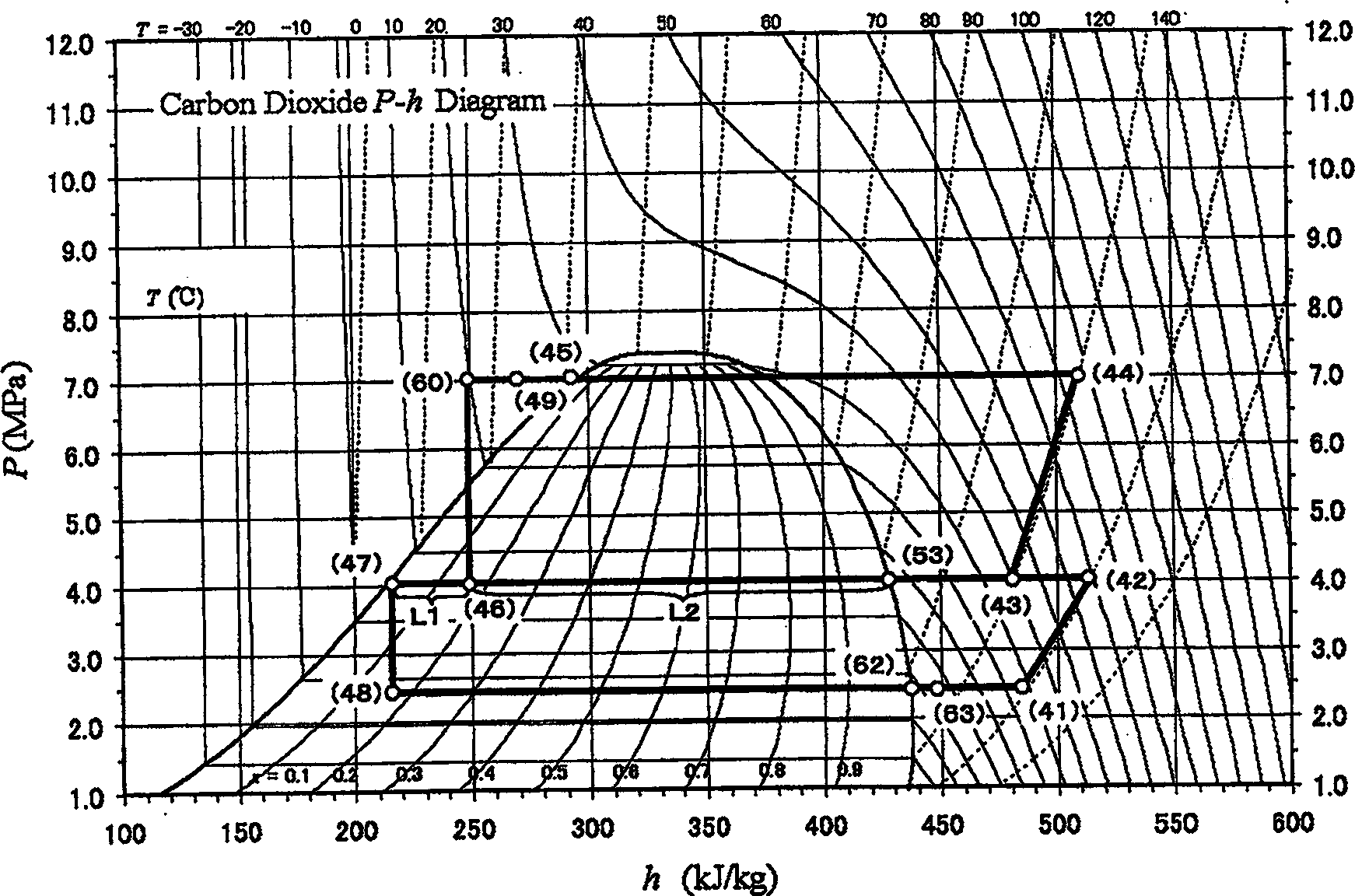
[0035] The refrigeration cycle apparatus 20 includes: a compressor 1; a radiator 2 connected to the discharge side of the compressor 1; and a first expansion valve as a decompression mechanism pr...
Embodiment approach 2
[0074] Next, refer to Figure 4 , to describe the second embodiment of the present invention. Figure 4 A side sectional view of refrigerator 70 showing this state. In addition, in Figure 4 In the refrigerator 30 of the above-mentioned first embodiment, the same reference numerals are used to perform the same or similar functions and effects. When compared with the refrigerator 30 of the above-mentioned first embodiment, the refrigerator 70 is different from the refrigerator 30 in that it has a refrigeration cycle device 21 that does not have the first heat exchanger 65 but Yes has a second heat exchanger 66 .
[0075] The second heat exchanger 66 is configured so that the liquid refrigerant separated by the gas-liquid separator 33 can exchange heat with the refrigerant from the heat absorber 14 . That is, the second heat exchanger 66 is formed between the refrigerant pipe 6C and the refrigerant pipe 6B. The second heat exchanger 66 can effectively supercool the liquid r...
Embodiment approach 3
[0077] Next, refer to Figure 5 , the third embodiment of the present invention will be described. Figure 5 A side sectional view of the refrigerator 90 showing this state. In addition, in Figure 5 Components with the same symbols as those in the above-mentioned embodiments have the same or similar functions and effects. When compared with the refrigerator 70 of the above-mentioned second embodiment, the refrigerator 90 is different from the refrigerator 70 in that it has the refrigeration cycle device 22 having the second heat exchanger 66, There is also a third heat exchanger 67 .
[0078] The third heat exchanger 67 is configured such that the refrigerant from the radiator 2 can exchange heat with the gas refrigerant separated by the gas-liquid separator 33 . That is, the third heat exchanger 67 is formed between the refrigerant pipe 6A and the refrigerant pipe 6D. Because through the third heat exchanger 67, in addition to obtaining the supercooling effect produced ...
PUM
 Abstract
Description
Claims
Application Information
 - R&D
- Intellectual Property
- Life Sciences
- Materials
- Tech Scout
- Unparalleled Data Quality
- Higher Quality Content
- 60% Fewer Hallucinations
Browse by: Latest US Patents, China's latest patents, Technical Efficacy Thesaurus, Application Domain, Technology Topic, Popular Technical Reports.
© 2025 PatSnap. All rights reserved.Legal|Privacy policy|Modern Slavery Act Transparency Statement|Sitemap|About US| Contact US: help@patsnap.com


