Dehumidifier

A technology for dehumidifiers and radiators, applied in heating methods, lighting and heating equipment, household appliances, etc., can solve problems such as condensation on the wall, and achieve the effect of preventing condensation and avoiding condensation

Inactive Publication Date: 2014-11-26
DAIKIN IND LTD
View PDF9 Cites 2 Cited by
  • Summary
  • Abstract
  • Description
  • Claims
  • Application Information

AI Technical Summary

Problems solved by technology

[0007] However, in the dehumidifier disclosed in Patent Document 1, dew condensation water generated in the evaporator is stored in the water storage tank at a low temperature, so the wall surface of the water storage tank is cooled, and dew condensation may occur on the wall surface.

Method used


Image

  • Dehumidifier
  • Dehumidifier
  • Dehumidifier

Examples


Embodiment Construction

[0043] Hereinafter, embodiments of the present invention will be described with reference to the drawings. The following embodiments are specific examples of the present invention and do not limit the technical scope of the present invention.

[0044] (1) Structure of the dehumidifier 10

[0045] (1-1) Appearance structure of the dehumidifier 10

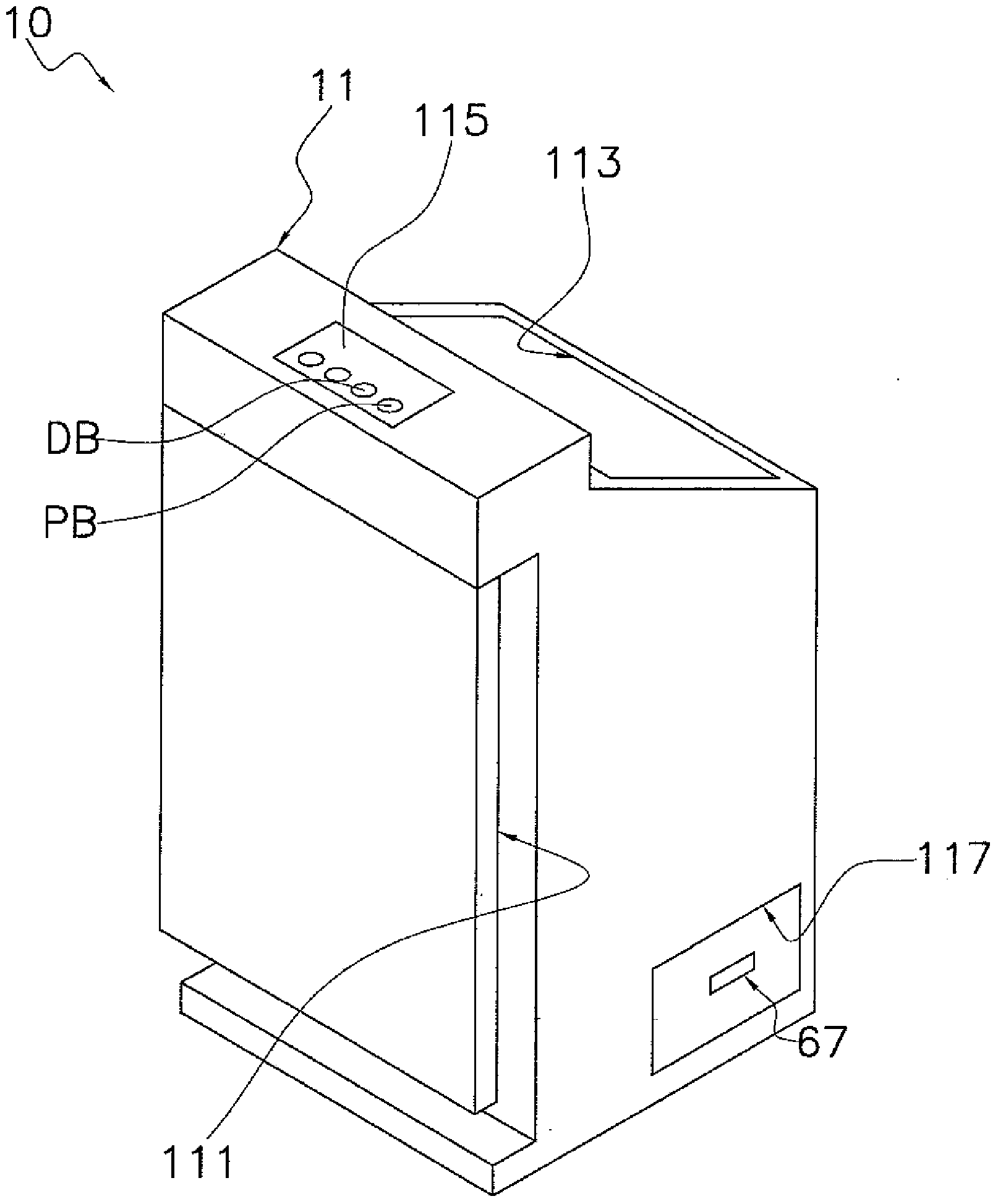
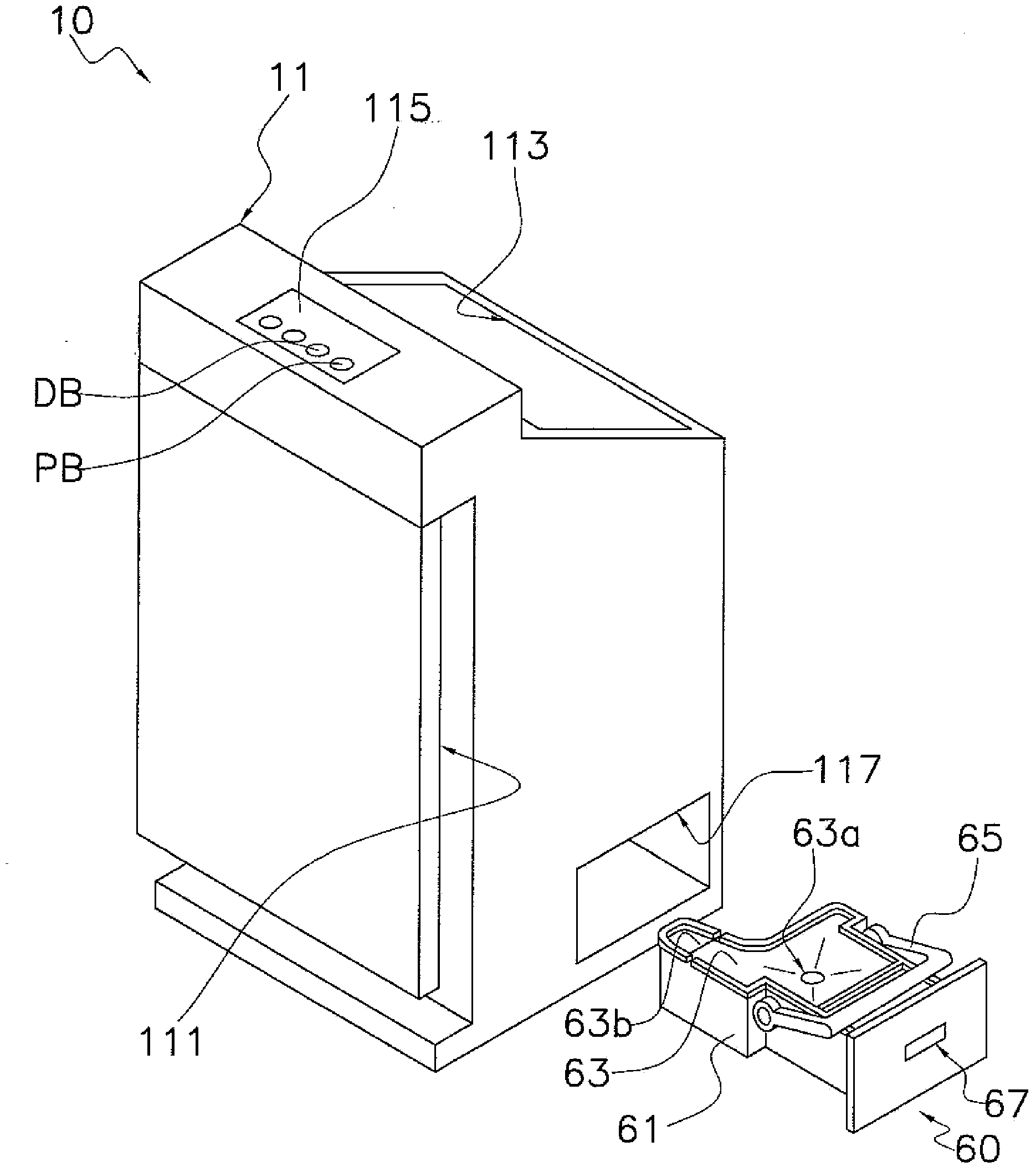
[0046] figure 1 It is an external perspective view of the dehumidifier 10 according to the embodiment of the present invention viewed from the upper right side to the front of the dehumidifier 10 . in addition, figure 2 From figure 1 A perspective view of the appearance of the dehumidifier 10 when the water storage tank 60 is removed. exist figure 1 and figure 2 Among them, the appearance structure of the dehumidifier 10 is formed by a main body casing 11 .

[0047] The main body case 11 has a suction port 111 , a blowing port 113 , an operation part 115 , and a tank insertion port 117 . Suction ports 111 for sucking air i...


PUM


Abstract

The invention discloses a dehumidifer which can increase the temperature of the moisture condensation to inhibit the condenstation on the all surface of the water storage tank; in the dehumidifier (10), the second water discharging plate (52) has a water guiding surface (50a) which is close to the lower end of the evaporation device (31) and the lower end in the condenser close to the evaporation device (31). As a particular structure, the water guiding surface (50a) has a first water bearing surface (50aa) opposite to the lower end of the evaporation device (31), and a second water bearing surface (50ab) opposite to the lower end of the condenser. The condensation water which is dropped on the water bearing surface (50aa) contacts with part of the condenser (37) and increases the temperature.

Description

technical field [0001] The invention relates to a dehumidifier, in particular to a dehumidifier utilizing a vapor compression refrigeration cycle. Background technique [0002] As a dehumidifier using a vapor compression refrigeration cycle, for example, in Patent Document 1 (Japanese Patent Application Laid-Open No. 5-79325), a method in which the evaporator and the condenser are placed on the upstream side of the condenser is disclosed. Dehumidifiers arranged in an airflow generated by a fan. In addition, a drain pan with a funnel-shaped section is arranged below the evaporator and the condenser. [0003] The air flow passing through the evaporator is cooled by heat exchange with the refrigerant flowing in the evaporator, so that moisture contained in the air flow condenses and adheres to the evaporator, so-called dew water. After the dew condensation water falls on the drain pan, it is recovered to the water storage tank arranged under the drain pan. [0004] prior art...

Claims


Application Information

Patent Timeline
Patent Type & Authority Applications(China)
IPC IPC(8): F24F1/02F24F13/22
Inventor 坂下朗彦清野竜二中泽武马
Owner DAIKIN IND LTD
Why Eureka
Try Eureka