Scroll compressor

A scroll compressor and movable scroll technology, applied in the field of scroll compressors, can solve the problems affecting the refrigeration efficiency of the scroll compressor and the high degree of superheat of the refrigerant, and achieve the effects of improving the efficiency of the refrigeration cycle and reducing the noise.

Inactive Publication Date: 2012-01-25
ANHUI MEIZHI COMPRESSOR
View PDF5 Cites 2 Cited by
  • Summary
  • Abstract
  • Description
  • Claims
  • Application Information

AI Technical Summary

Problems solved by technology

[0004] The technical problem to be solved by the present invention is to provide a scroll compressor to solve the problem that the overheating of the refrigerant in the existing scroll compressor affects the refrigeration efficiency of the scroll compressor

Method used


Image

  • Scroll compressor
  • Scroll compressor
  • Scroll compressor

Examples


Embodiment Construction

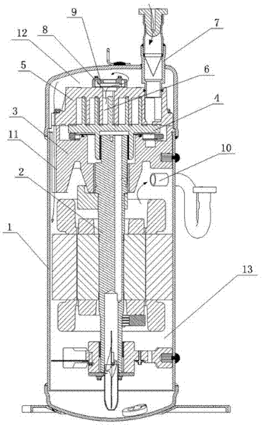
[0012] See figure 1 , a scroll compressor, including a shell 1, a crankshaft 2 set in the shell 1, a frame 3 set on the crankshaft 2, a movable scroll 4 set on the top of the crankshaft 2 and above the frame 3, and a set The fixed scroll 5 above the movable scroll 4 and meshed with the movable scroll 4 communicates with the compression chamber 6 formed on the fixed scroll 5 and meshed with the movable scroll 4 and the fixed scroll 5 The suction pipe 7, the exhaust hole 8 arranged on the top of the fixed scroll 5 and communicated with the central compression chamber 6, the exhaust check mechanism 9 arranged on the top of the fixed scroll 5 and communicated with the exhaust hole 8 and arranged on the machine The exhaust pipe 10 below the frame 3, the suction pipe 7 and the exhaust pipe 10 all extend out of the housing 1;

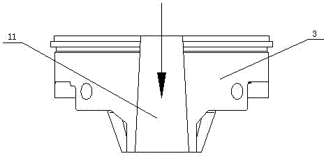
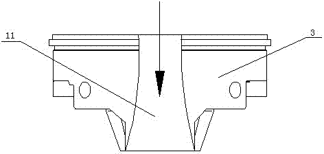
[0013] See figure 2 , image 3 , the outer wall of the frame 3 is provided with an exhaust channel 11, the exhaust channel 11 is a gradually expanding str...


PUM


Abstract

The invention discloses a scroll compressor, which comprises a shell, a crank shaft, a stander, a movable scroll disc, a fixed scroll disc, a gas suction pipe, an exhaust hole, an exhaust return stop mechanism and an exhaust pipe, wherein the crank shaft is arranged in the shell; the stander is arranged on the crank shaft; the movable scroll disc is arranged at the top end of the crank shaft and is positioned above the stander; the fixed scroll disc is arranged above the movable scroll disc and is mutually engaged with the movable scroll disc; the gas suction pipe is arranged on the fixed scroll disc and is communicated with a compression chamber which is formed by engaging the movable scroll disc with the fixed scroll disc; the exhaust hole is formed in the top of the fixed scroll disc and is communicated with the central compression chamber; the exhaust return stop mechanism is arranged above the fixed scroll disc and is communicated with the exhaust hole; the exhaust pipe is arranged below the stander; both the gas suction pipe and the exhaust pipe extend out of the shell; the outer wall of the stander is provided with an exhaust passage; and the exhaust passage has a divergent structure from top to bottom. The scroll compressor has a simple structure; only the groove shape of the exhaust passage is required to be changed; through the structure of the exhaust passage, the flow velocity for flowing a refrigerant into a low-pressure chamber is reduced, which contributes to oil-gas separation, and the noise level is reduced; and meanwhile, the degree of superheat of the refrigerant which enters the low-pressure chamber is reduced, so that the refrigeration cycle efficiency of the refrigerant is increased.

Description

[0001] technical field [0002] The invention relates to the field of scroll compressors, in particular to a scroll compressor capable of reducing the superheat of refrigerant. Background technique [0003] The flow path of the refrigerant in the scroll compressor is firstly from the suction pipe into the compression chamber formed by the meshing of the movable scroll and the fixed scroll, and the movable scroll revolves around the crankshaft driven by the crankshaft. During the revolution, the refrigerant obtains energy in the multiple pairs of compression chambers formed by the movable scroll and the fixed scroll, and then is discharged to the high-pressure chamber through the exhaust check mechanism, then enters the low-pressure chamber through the exhaust passage of the frame, and finally passes through the exhaust The gas pipe discharges into the condenser to participate in heat exchange. When the refrigerant flows from the high-pressure chamber into the low-pressure c...

Claims


Application Information

Patent Timeline
IPC IPC(8): F04C18/02F04C29/04
Inventor 严黎坚
Owner ANHUI MEIZHI COMPRESSOR
Why Eureka
Try Eureka