Collision bumper for optical mechanical module, and movable lenses

An opto-mechanical module and lens movement technology, applied in the focusing device of a projector, the focusing device of a camera, a projection device, etc., can solve the problems of increasing the assembly complexity of the opto-mechanical module and the volume of the opto-mechanical module, and reduce the assembly complexity. The effect of stability, space saving and volume reduction

Inactive Publication Date: 2006-12-06
ASUSTEK COMPUTER INC
View PDF0 Cites 3 Cited by
  • Summary
  • Abstract
  • Description
  • Claims
  • Application Information

AI Technical Summary

Problems solved by technology

[0006] 2. Use complex elastic components to increase the assembly complexity of the optical-mechanical module
[0007] 3. Due to the configuration of the elastic components, the volume of the optical-mechanical module is too large

Method used


Image

  • Collision bumper for optical mechanical module, and movable lenses
  • Collision bumper for optical mechanical module, and movable lenses
  • Collision bumper for optical mechanical module, and movable lenses

Examples


Embodiment Construction

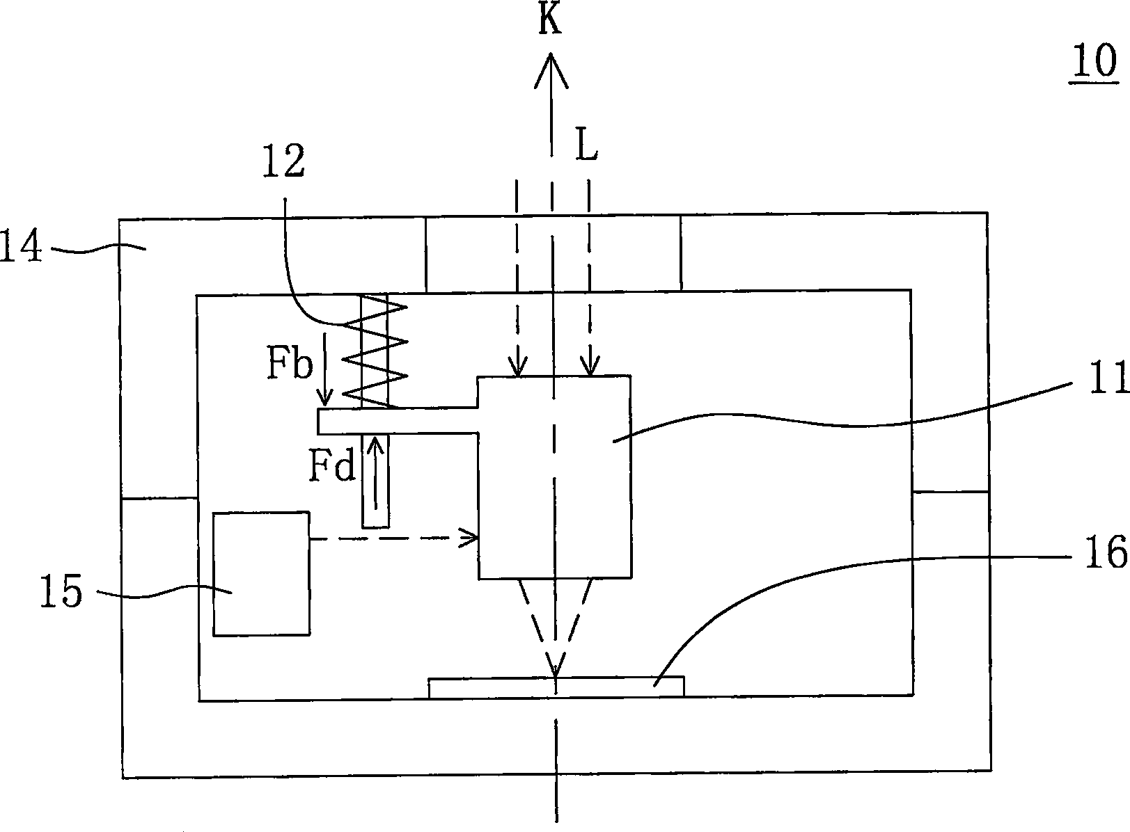
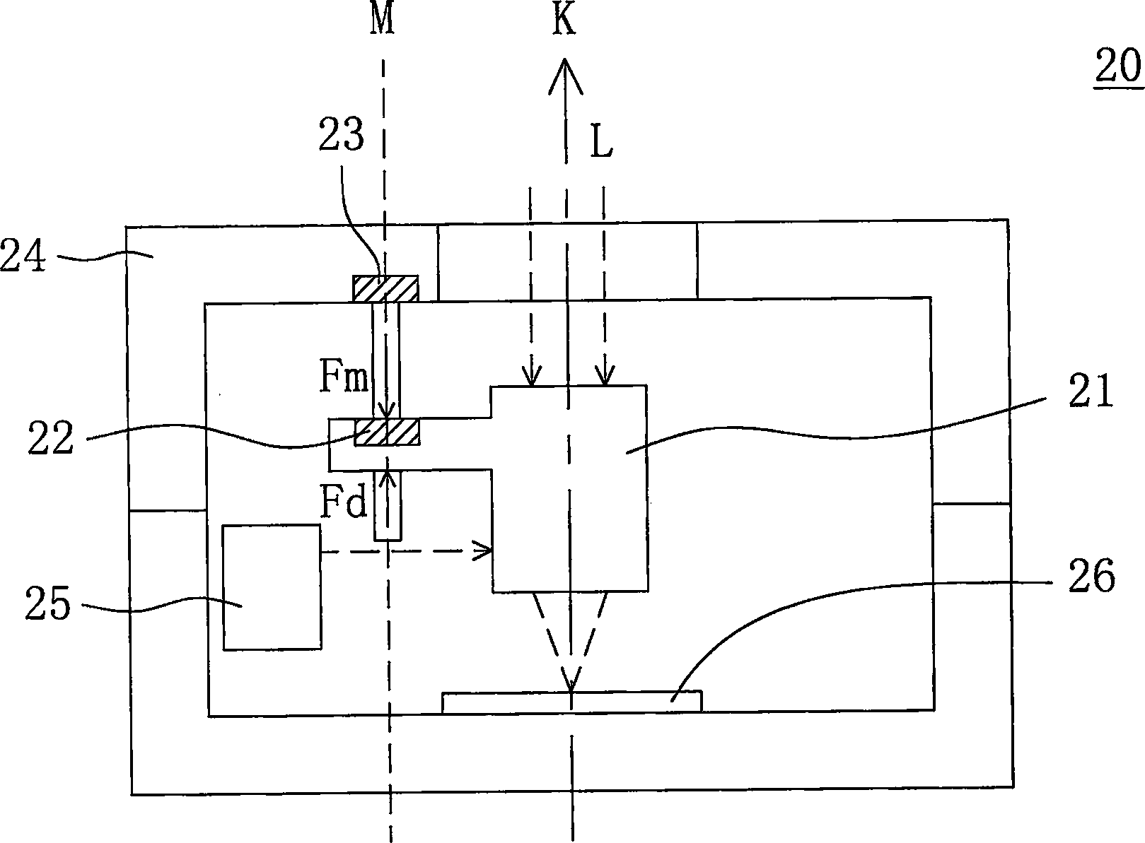
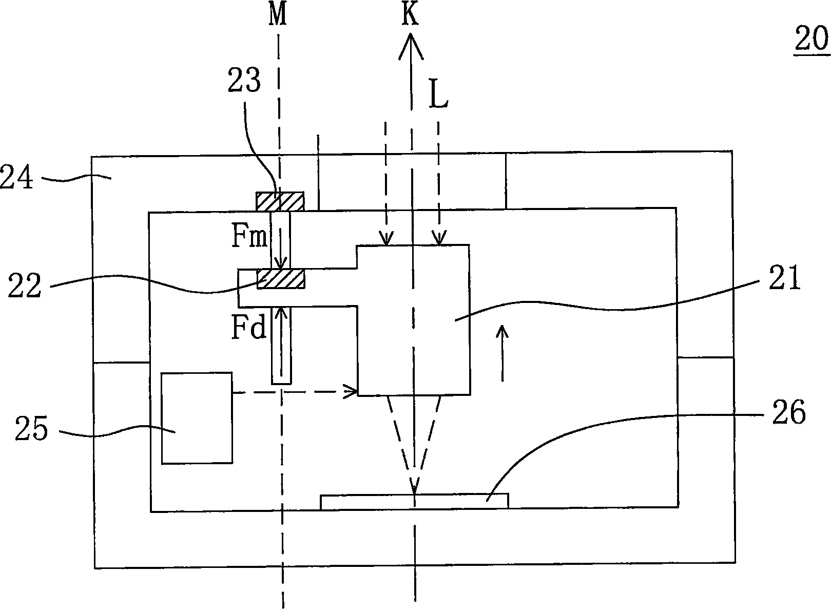
[0031] In order to make the above-mentioned purpose, features, and advantages of the present invention more obvious and easy to understand, a preferred embodiment is given below, and the implementation of the optical-mechanical module and its lens moving buffer device of the present invention will be described in detail below in conjunction with the accompanying drawings as follows,

[0032] The present invention proposes a lens movement buffer device used in an optical-mechanical module, which is used to replace the traditional contact spring mechanism to provide the buffer force required for lens movement. In addition, based on the same operating principle, the present invention can be applied to optical lens modules of various digital cameras and mobile phones with digital camera functions.

[0033] Please refer to Figure 2A , which shows a schematic cross-sectional view of an optical-mechanical module according to a preferred embodiment of the present invention. The opt...


PUM


Abstract

The invention relates to an optical-machine module and the lens moving buffer device that includes lens, actuator, the first magnetic component and the second magnetic component. The actuator supplies a thrust to drive the lens along optical axis direction. And the first magnetic component is set on the lens. The second magnetic component generates a magnetic reverse thrust along optical direction between the first magnetic component and the second magnetic component. When the actuator drives the lens, the second magnetic component supplies reverse thrust as the buffer power for lens. The non-contact magnetic component takes the place of contact flexible component to avoid the noise and decrease the installing complex. It could effectively save space and decrease volume of the optical-machine module.

Description

technical field [0001] The invention relates to an optical-mechanical module and its lens moving buffer device, in particular to an optical-mechanical module and its lens moving buffering device using magnetic force as the buffer force required for lens movement. Background technique [0002] In the optical-mechanical module of a general digital camera, the power required for moving the lens is mainly provided by an actuator. In order for the lens to move back and forth to focus the image on the sensor, a buffer force is usually required as the force for the lens to return. [0003] Please refer to figure 1 , which shows a schematic cross-sectional view of a traditional opto-mechanical module using a spring to generate a buffer force. In the optical-mechanical module 10, the lens 11 is pushed by the driving force Fd generated by the actuator 15 to move along the optical axis direction K, and at the same time, the buffer force Fb generated by the spring 12 is used as the re...

Claims


Application Information

Patent Timeline
Patent Type & Authority Applications(China)
IPC IPC(8): G03B3/10
Inventor 陈泳全李宜明陈彦光
Owner ASUSTEK COMPUTER INC
Why Eureka
Try Eureka