

Method of reducing sand production from a wellbore
A wellbore and perforation technology, applied in the direction of wellbore/well components, drilling equipment and methods, earthwork drilling and production, etc., can solve problems such as clogging of holes, screens or sandstone filter layers, reduction of fluid products, etc.
- Summary
- Abstract
- Description
- Claims
- Application Information
AI Technical Summary
Problems solved by technology
Method used
Image

Examples
Embodiment Construction
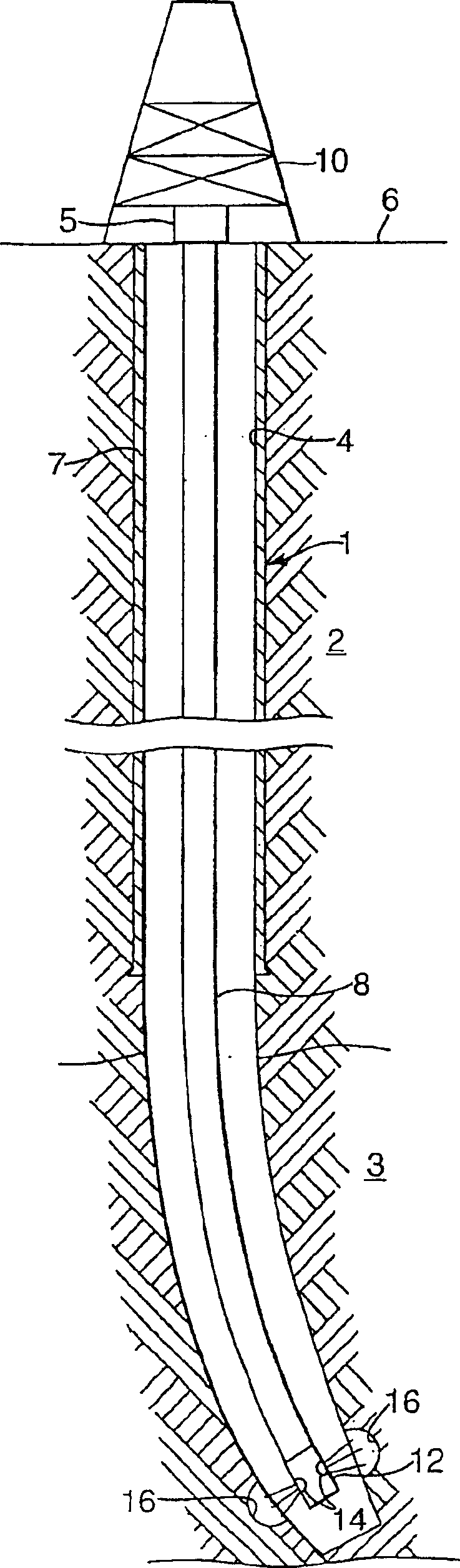
[0030] Figure 1A A wellbore 1 for producing hydrocarbon fluids is shown extending into a formation 2 comprising a formation zone 3 containing hydrocarbon fluids. The wellbore 1 is provided with a casing 4 extending from a wellhead 5 on the surface 6 to an upper end near the formation zone 3 . The casing 4 is fixed in the borehole by a cement layer 7 between the borehole wall and the casing 4 . A water injection string 8 for injecting cutting fluid extends into the wellbore 1 from a drilling rig 10 on the surface. The water injection string 8 is provided at its lower end with a fluid jet cutter 12 having a pair of nozzles 14 disposed opposite to each other. A fluid jet cutter 12 is located near the lower end of the formation zone 3 . A fluid jet 16 is sprayed from the nozzle 14 towards the wall of the borehole 1, thus creating a slot 16 oppositely arranged on the borehole wall.
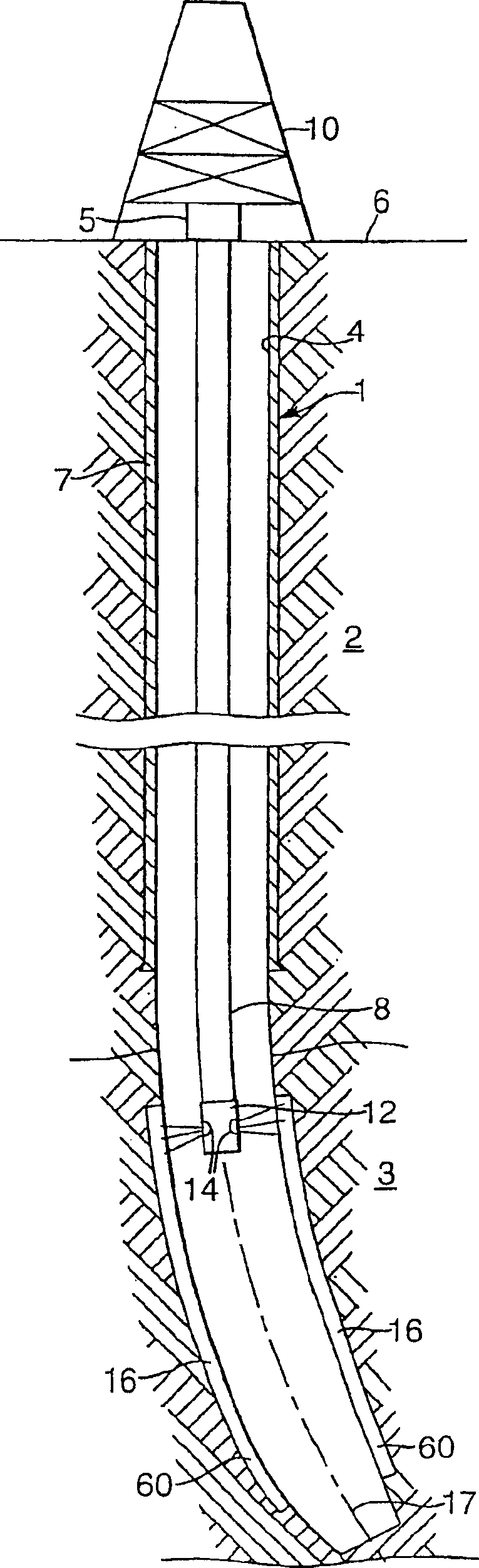
[0031] Figure 1B Wellbore 1 is shown with water injection string 8 raised to a position where...
PUM
 Abstract
Description
Claims
Application Information