
Workpiece transmission device

A technology for conveying devices and workpieces, which is applied to metal processing machinery parts, manufacturing tools, metal processing, etc., can solve the problems of prolonged processing time, workers cannot easily feed in/take out workpieces, poor accessibility, etc., and achieve improved accessibility Effect

Inactive Publication Date: 2006-12-20
KOMATSU NTC LTD
View PDF3 Cites 9 Cited by
  • Summary
  • Abstract
  • Description
  • Claims
  • Application Information

AI Technical Summary

Problems solved by technology

For the worker, the accessibility of the workpiece processing position is poor, which brings about the problem that the worker cannot easily feed in / take out the workpiece
It takes a certain amount of time to advance the workpiece support table to the workpiece processing position and to retract the workpiece support table from the workpiece processing position, resulting in prolonged processing time

Method used


Image

  • Workpiece transmission device
  • Workpiece transmission device
  • Workpiece transmission device

Examples


Embodiment Construction

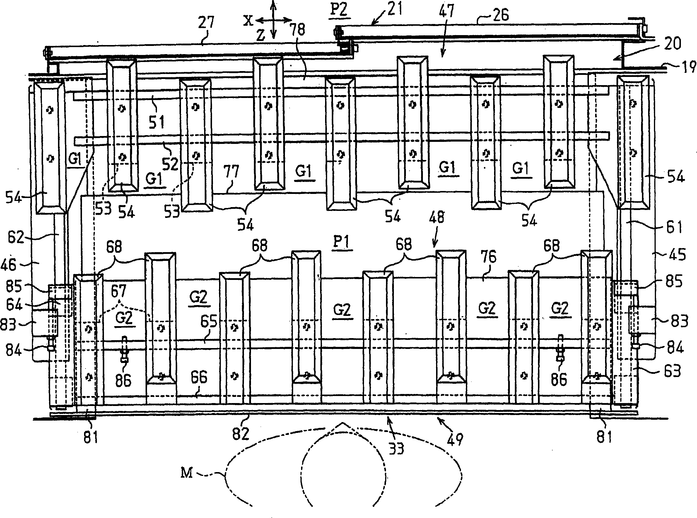
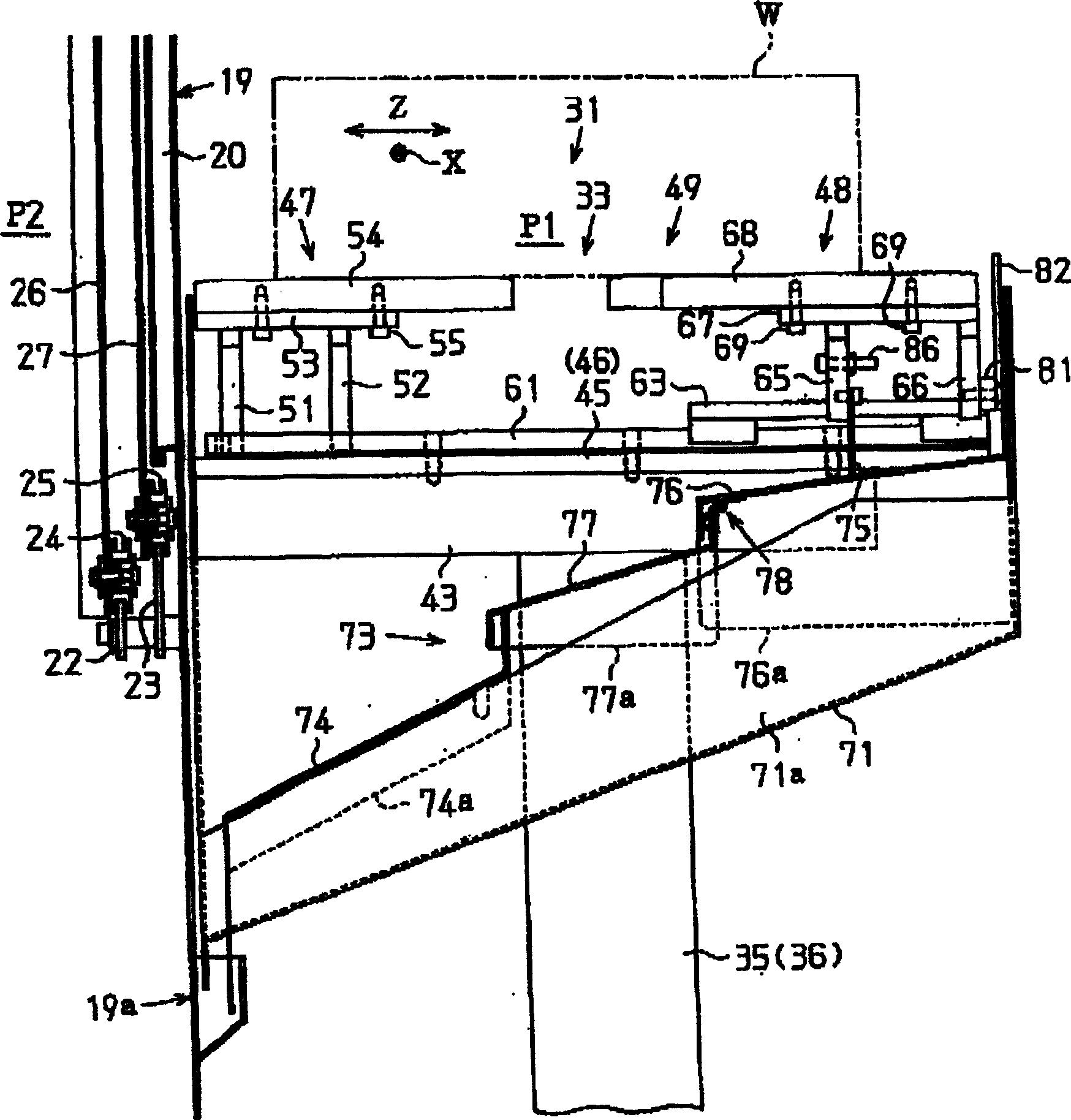
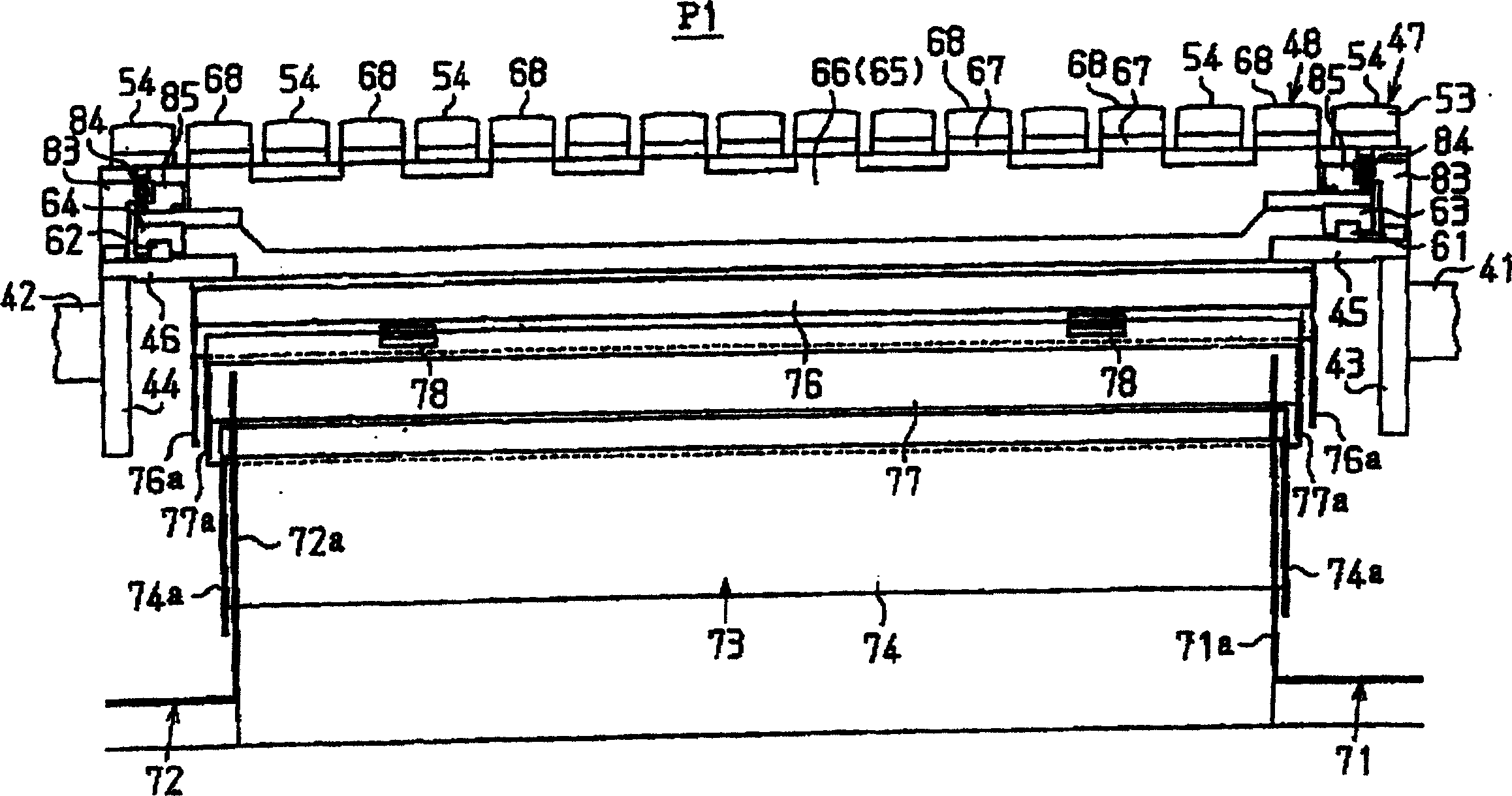
[0044] Below, refer to Figure 1 to Figure 8 , describing a workpiece transfer device according to an embodiment of the present invention.

[0045] Such as Figure 7 As shown, the support base 12 is vertically installed on the upper surface of the bed 11 . Such as Figure 8 As shown, through a pair of left and right bearings 13 , 13 , the workpiece support table 14 is installed on the upper surface of the support base 12 in a manner that can be indexed and rotated by a servo motor 15 . On the upper surface of the workpiece supporting table 14, clamping mechanisms 16 for clamping the workpiece W are provided at a plurality of positions. Such as Figure 7 As shown, the front side wall of the support base 12 ( Figure 7 The center is the right side wall), and the guide plate 18 is horizontally supported by the mounting post 17 for guiding the workpiece W when the workpiece is sent into / out of the workpiece support table 14 side. A machining device (not shown) is installed o...


PUM


Abstract

The invention provides a workpiece transfer device, wherein a fixed table (47) constituting a transfer table (49) is arranged in front of a machining position (P2) in a machine tool. The movable workbench (48) constituting the transfer workbench (49) is arranged in front of the fixed workbench (47). A gap (G1) is provided between the fixing rods (54) of the fixing table (47). A gap (G2) is provided between the movable rods (68) of the movable table (48). The movable rod (68) is configured to be advanced into the gap (G1), and the fixed rod (54) is configured to be advanced into the gap (G2). The workpiece is supported on the fixed workbench (47) and the movable workbench (48), so that the movable workbench (48) moves to the side of the fixed workbench (47), so that the transfer workbench (49) changes from the extended state to the contracted state , so as to transport the workpiece to the machining position in the machine tool.

Description

technical field [0001] The invention relates to a workpiece conveying device in a machine tool. Background technique [0002] Generally, in a machine tool, a processing device having a spindle device on a bed is installed, and a workpiece support table is arranged at a processing position in front of the processing device to support the workpiece. The workpiece conveying device is installed in front of the workpiece support worktable, and is used to send the unprocessed workpieces that have not yet been processed to the workpiece support workbench from the workpiece in / out position on the conveyor line, and the conveyor line feeds the unprocessed workpieces , is also used to ship out processed workpieces. If the worker manually feeds in / takes out the workpiece between the workpiece transfer device and the workpiece support table, when the workpiece transfer device is fixed, the worker transports the workpiece from the workpiece in / out position on the conveyor line to the wo...

Claims


Application Information

Patent Timeline
IPC IPC(8): B23Q7/00B23Q1/03B23Q1/25B23Q11/08B23Q11/00B23Q41/02
Inventor 屉田星辉中岛利晴
Owner KOMATSU NTC LTD
Learn More