Hand-operated binder

A technology of binding machine and frame, applied in binding, printing, metal processing and other directions, can solve the problems of troublesome operation, low reliability, and difficulty in obtaining the length of the binding tube, and achieves a simple structure, convenient riveting operation, and simple operation. Effect

Inactive Publication Date: 2006-12-20
阮永华
View PDF0 Cites 4 Cited by
  • Summary
  • Abstract
  • Description
  • Claims
  • Application Information

AI Technical Summary

Problems solved by technology

[0003] In order to overcome the problems of low reliability, complex structure, cumbersome operation, and difficulty in obtaining a suitable binding tube length in the manual binding machine in the prior art, the paper pressing mechanism of the present invention provides a paper pressing mechanism with high reliability, simple structure and simple operation. A manual binding machine that can get a suitable binding tube length

Method used


Image

  • Hand-operated binder
  • Hand-operated binder
  • Hand-operated binder

Examples


Embodiment 1

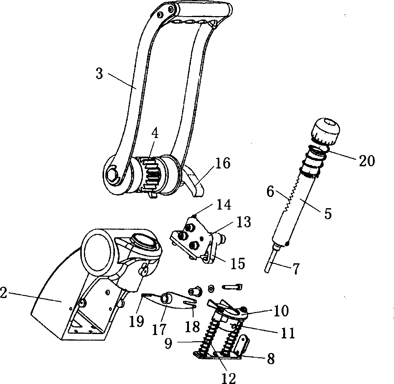
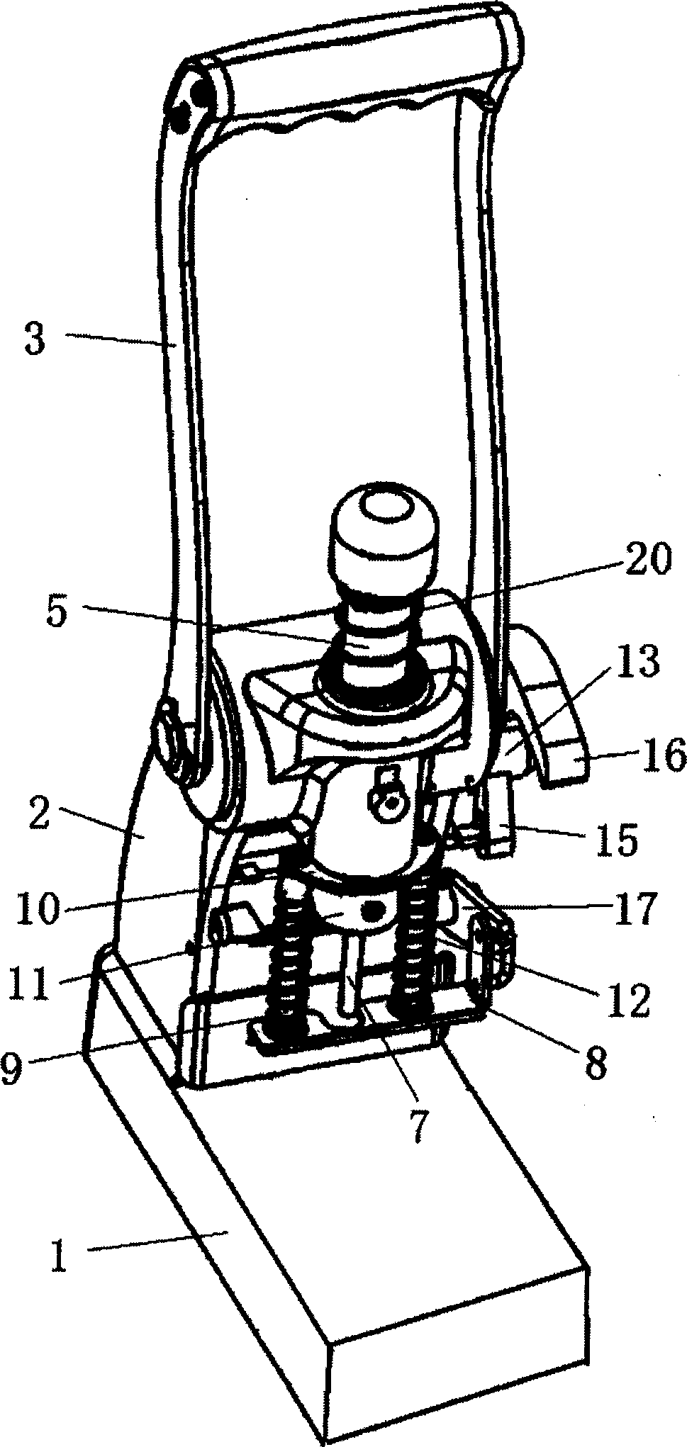
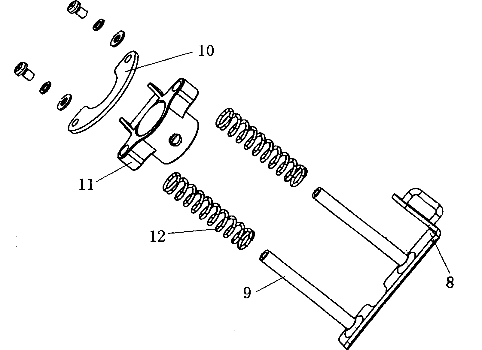
[0020] refer to Figure 1-3 , a manual binding machine, comprising a base 1, a frame 2 mounted on the base 1, an operating handle 3 hinged to the frame 2, the operating handle 3 is fixedly connected to a hinge shaft, and the hinge shaft There is a gear 4 on it, and a guide post 5 that can slide up and down is set inside the frame 1. The guide post 5 has a tooth mouth 6 that cooperates with the gear 4, and a drill is installed at the lower end of the guide post 5. 7. There is a cardboard 8 between the base 1 and the frame 2, the cardboard 8 has a guide rod 9 extending upward, and the upper end of the guide rod 9 is fixed to the baffle 10 through screws and nuts, The baffle 10 has an opening through which the guide post 5 can pass; the guide rod 9 is covered with a connecting sleeve 11 that can slide up and down, and the connecting sleeve 11 is located below the baffle 10 , the connecting sleeve 11 and the lower part of the guide column 5 are fixedly connected by screws; the gu...

Embodiment 2

[0024] refer to Figure 1-4 , the frame 2 is equipped with a knife seat 13, the knife seat 13 is provided with a slidable blade 21, the knife seat 13 is provided with a through hole 14 for inserting a pipe, and the through hole 14 is located in the On the outside of the edge of the blade 21, the knife seat 13 is also hinged with a shifting block 15 for controlling the sliding of the blade 21, and the operating handle 3 is fixedly connected with a shifting fork 16 matched with the shifting block 15;

[0025] The frame 2 below the knife block 13 is hinged with a lever 17, the front end 18 of the lever 17 is affixed to the pressboard 8, and the rear end 19 of the lever 17 has a supporting point of a pipe. The lower end of the tube is a reserved section, and the distance from the upper end of the reserved section to the blade 21 is equal to the distance from the pressboard 8 to the base 1 .

[0026] All the other structures are the same as in Embodiment 1.

[0027] The manual bi...

Embodiment 3

[0030] refer to Figure 1-4 , there are two guide rods 9, symmetrically located on both sides of the guide post 5. Symmetrically setting the guide rods 9 is conducive to uniform force. The rest of the structures and implementations are the same as in Embodiment 2.

[0031] Embodiment Three

[0032] refer to Figure 1-4 , The upper end of the guide post 5 is also equipped with a return spring 20 . The significance of setting the back-moving spring 20 is that the guide post 5 can be reset automatically after the operation is completed.


PUM


Abstract

The invention relates to a hand-operated binder, which comprises a base, a frame mounted on the base, and an operation handle hinged with frame, wherein said operation handle is fixed with hinge axle; the hinge axle is arranged with gear; the frame is sheathed with guide post sliding up and down; said guide post has the tooth cut matched with the gear; the lower end of guide post is mounted with drill lip; the compress plate is between the base and the frame; said compress plate via elastic body is connected to the guide post; in addition, the invention also comprises a cutter base for cutting binding tube. The invention has the advantages that: 1, the compress plate moves with the motions of guide post and drill lip, to compress downwards until naturally positioning document; 2, the inventive structure is simple; 3, the compress plate automatically moves with guide post and drill lip, with simple operation; 4, drilling hole on the document and completing cutting tube, with right cut length, to support the punch operation.

Description

(1) Technical field [0001] The invention relates to a manual binding machine. (2) Background technology [0002] Many occasions such as finance and file management need to bind documents. The main structure of the existing manual binding machine is: comprising a base, a frame installed on the base, and an operating handle hinged with the frame. The hinge shaft is fixed, and the hinge shaft is equipped with a gear, and the gear is matched with the rack, and the rack can slide up and down to cover the frame, and a drill is installed at the lower end of the rack. There is a paper pressing mechanism below the drill. The paper pressing mechanism is used for pressing down and positioning the documents during stapling, and includes a paper pressing board, a spring and a locking mechanism for locking the paper pressing board. When in use, place the document under the drill, first press the cardboard down to compress the document, then lock the cardboard, position the document, and...

Claims


Application Information

Patent Timeline
Patent Type & Authority Applications(China)
IPC IPC(8): B26F1/02B26D5/10B26D7/08B26D7/27B42F3/00
Inventor 阮永华
Owner 阮永华
Why Eureka
Try Eureka