Optical system capable of shortening optical path and lens imaging quality detection system

A quality inspection and optical system technology, applied in the field of optical systems, can solve problems such as inconvenient measurement, no economic benefits, and large structure, and achieve the effect of reducing the length

Inactive Publication Date: 2006-12-20
DUAL HALO TECH +1
View PDF0 Cites 4 Cited by
  • Summary
  • Abstract
  • Description
  • Claims
  • Application Information

AI Technical Summary

Problems solved by technology

[0002] see figure 1 , shows the structural diagram of a known optical system for lens imaging quality testing. The most commonly used testing method for lens imaging quality is to use a standardized sample 100 as an object to be viewed, and the sample 100 is imaged on the lens 110 to be tested. An image detection component 120, therefore, in the measurement step, the template 100 must be set at different distances from the lens 110 to be tested for measurement, but the measurement conditions are: no matter how far the template 100 is from the lens 110 to be tested, The size of the image formed by each template 100 through the lens under test 110 must be the same. Therefore, in order to satisfy this condition, the size of the template 100 must change as the distance between the position of the template 100 and the lens 110 under test increases. be larger, so as to meet the above measurement conditions, such as figure 1 The size of the three templates 100 in 100a, 100b, and 100c increases with the distance from the lens 110 to be tested, and the size of the template 100 becomes larger and larger. In this way, it is quite uneconomical, and the space required for measurement and the replacement of the template 100 The time and manpower required will cause the inconvenience of measurement and the huge space for equipment
Related technologies such as China Taiwan Patent Publication No. M253795 and No. M253796 patents disclose a track-type focus detection box and a focus detection box for camera lenses, both of which are structures for replacing the template and mainly for adjusting the template structure. This structure can only be used for short-distance measurement. If the measurement distance needs to be several meters long, this structure will become very large

Method used


Image

  • Optical system capable of shortening optical path and lens imaging quality detection system
  • Optical system capable of shortening optical path and lens imaging quality detection system
  • Optical system capable of shortening optical path and lens imaging quality detection system

Examples


Embodiment Construction

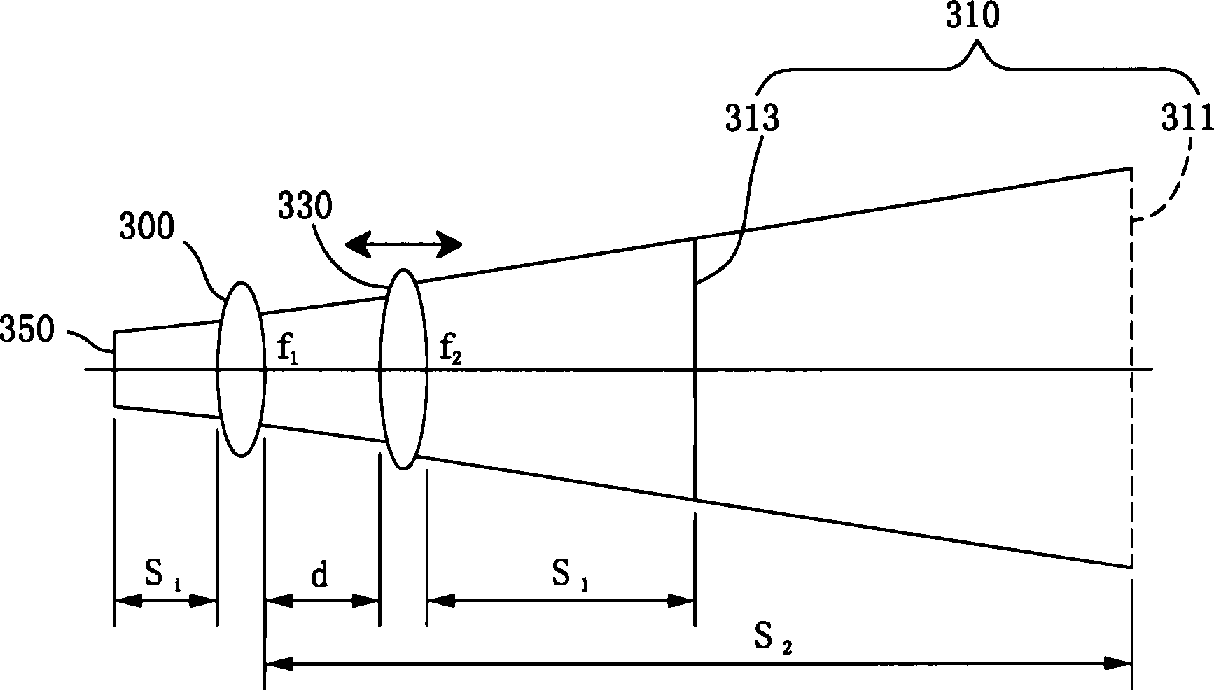
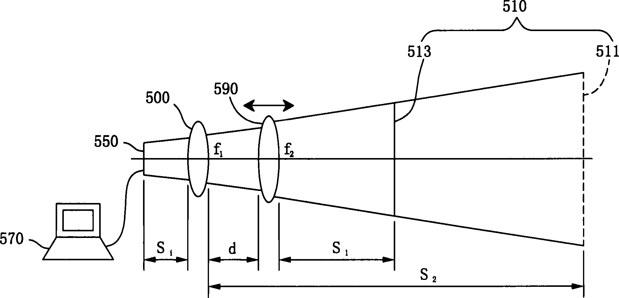
[0051] see figure 2, shows the structural diagram of the optical system shortening the optical path of the present invention. The present invention is an optical system shortening the optical path. By adding an equivalent lens 330, the optical path is shortened, so that the volume of the entire optical system can be reduced.

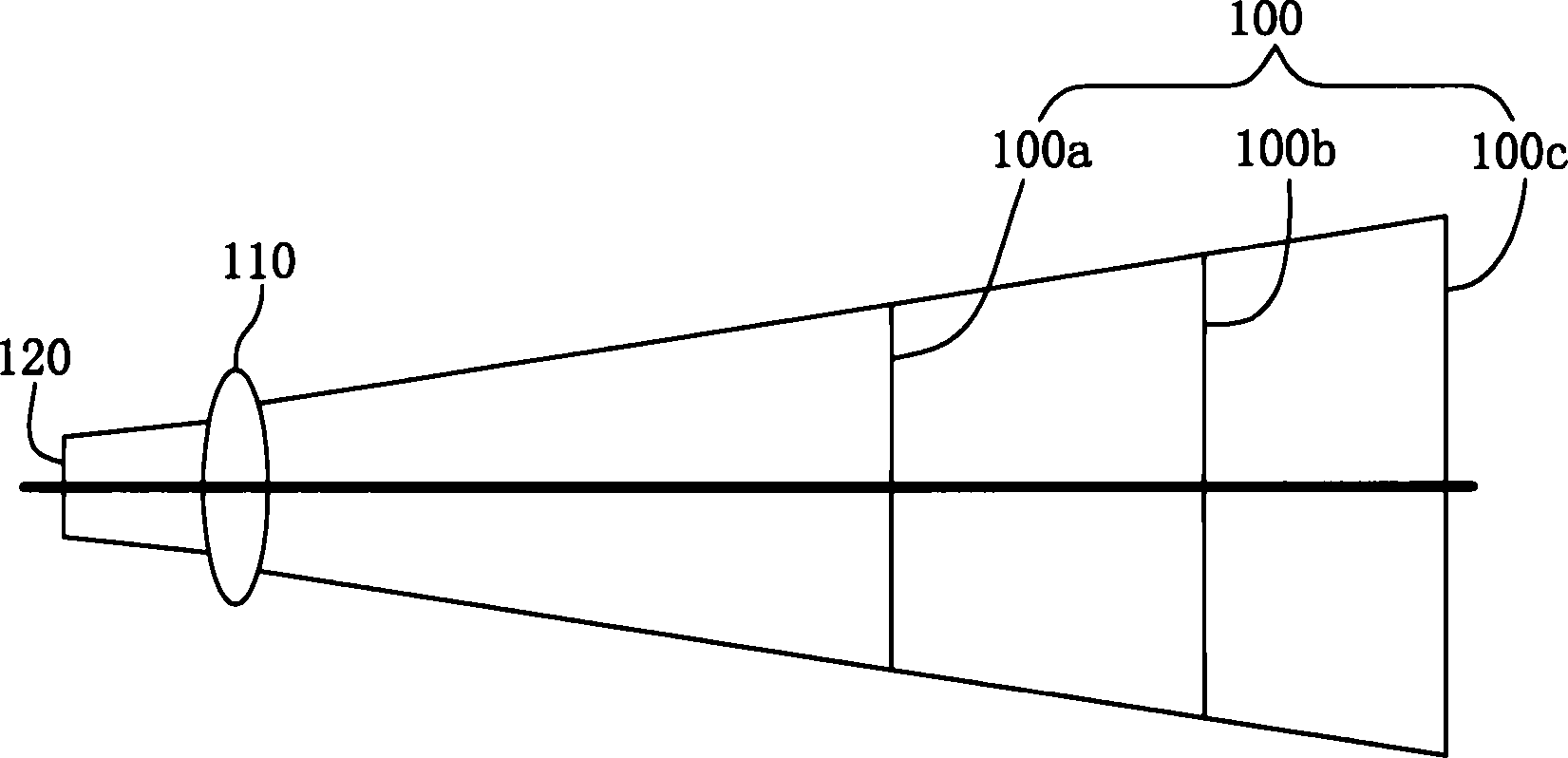
[0052] The optical system for shortening the optical path of the present invention includes an imaging lens 300, and an object 310 is placed on one side of the imaging lens 300, the object 310 includes an original object 311 and an equivalent object 313, and the original object 311 and the imaging lens The interval between 300 is the original object distance S 2 Therefore, the original object 311 can generate an original image (not shown) on the imaging surface 350 through the imaging lens 300 .

[0053] An equivalent lens 330 is added between the object 310 and the imaging lens 300, and the equivalent lens 330 is separated from the equivalent object 3...


PUM


Abstract

The invention discloses an optical path shortening optical system and lens imaging quality detecting system, which is characterized by the following: shortening optical path between object and imaging lens through adding one equivalent lens; satisfying different positions of imaging lens; mating the same size object to adjust gap of equivalent lens and imaging lens.

Description

technical field [0001] The invention relates to an optical system, in particular to an optical system capable of shortening the optical path and a lens imaging quality detection system. Background technique [0002] see figure 1 , shows the structural diagram of a known optical system for lens imaging quality testing. The most commonly used testing method for lens imaging quality is to use a standardized sample 100 as an object to be viewed, and the sample 100 is imaged on the lens 110 to be tested. An image detection component 120, therefore, in the measurement step, the template 100 must be set at different distances from the lens 110 to be tested for measurement, but the measurement conditions are: no matter how far the template 100 is from the lens 110 to be tested, The size of the image formed by each template 100 through the lens under test 110 must be the same. Therefore, in order to satisfy this condition, the size of the template 100 must change as the distance bet...

Claims


Application Information

Patent Timeline
Patent Type & Authority Applications(China)
IPC IPC(8): G02B15/10G01M11/02
Inventor 林世穆
Owner DUAL HALO TECH
Why Eureka
Try Eureka