

Element mounting device
A technology for installing devices and components, applied in electrical components, electrical components, etc., can solve problems such as non-uniformity, and achieve the effect of stable component supply and reliable adsorption
- Summary
- Abstract
- Description
- Claims
- Application Information
AI Technical Summary
Problems solved by technology
Method used
Image

Examples
Embodiment Construction
[0024] Hereinafter, the present invention will be specifically described with reference to the drawings.
[0025] (Example)
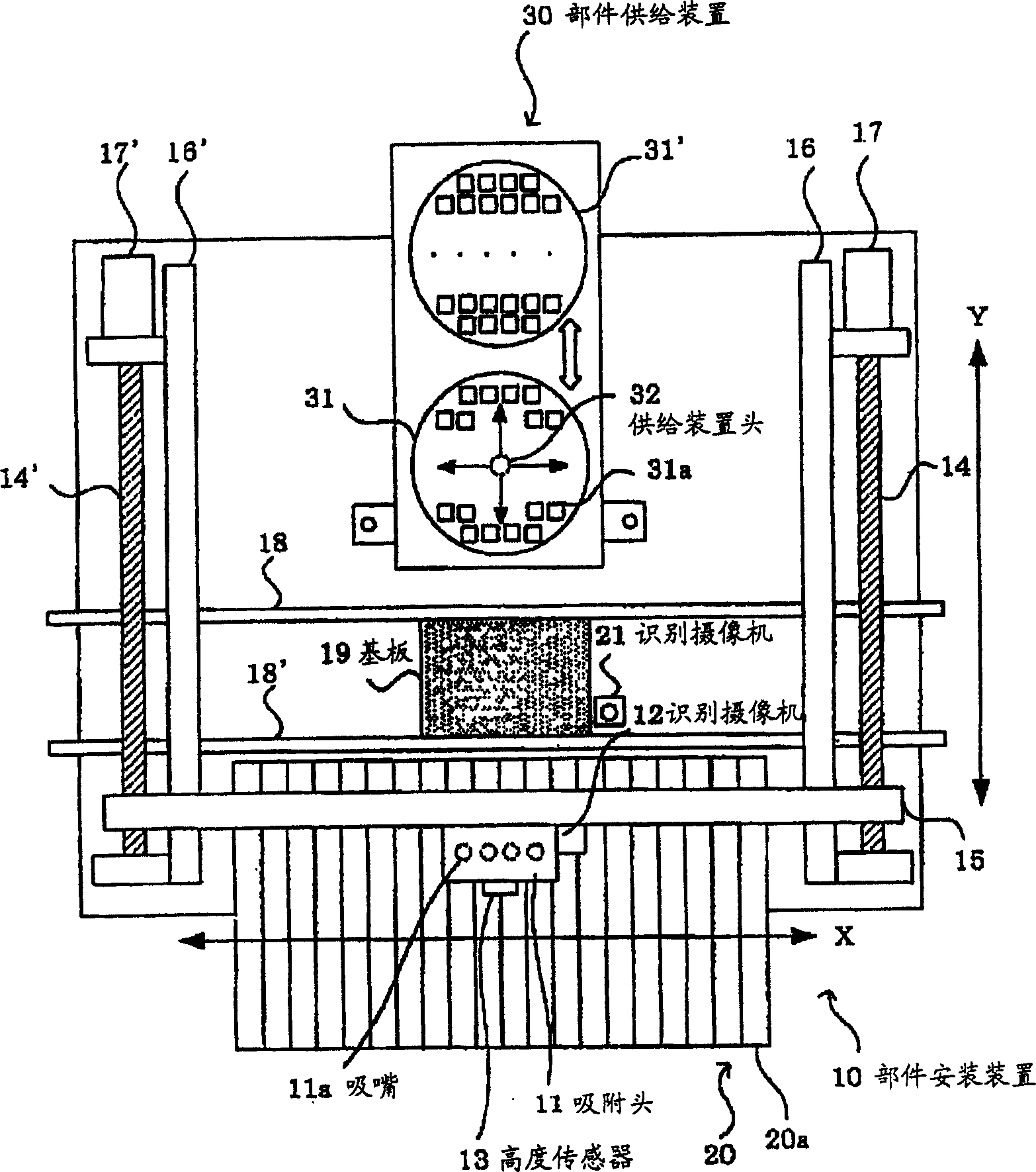
[0026] exist figure 1 In FIG. 2 , a component mounting device 10 and an external wafer component supply device 30 that supplies wafer components to the component mounting device are shown. The component mounting device 10 is provided with a suction head 11 which can move in the X-axis direction along an X-axis guide rail 15 by an X-axis motor (not shown). The X-axis guide rail 15 is combined with the screw shafts 14, 14', and the Y-axis motors 17, 17' are used to rotate the screw shafts, so that the X-axis guide rail 15 moves in the Y-axis direction along the Y-axis guide rails 16, 16'.
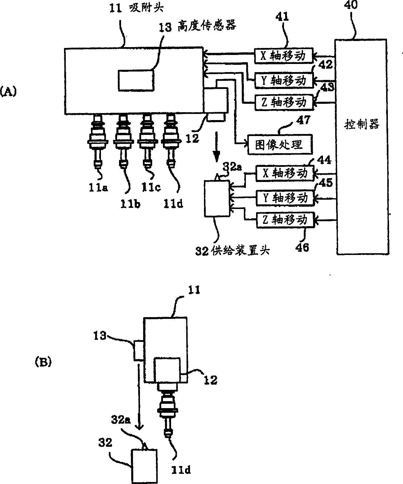
[0027] use figure 2 The symbol 41 in (A) represents the X-axis moving unit such as the X-axis motor and the X-axis guide rail 15, and the symbol 42 represents the Y-axis motor 17, 17', the screw shaft 14, 14', and the Y-axis guide rail 16, 16'. Wait for the Y axi...
PUM
 Abstract
Description
Claims
Application Information