
Wheel bearing unit embodied as an angular contact ball bearing

A technology of angular contact ball bearings and wheel bearings, applied in rolling contact bearings, bearings, wheels, etc., can solve the problems of inaccurate position of brake calipers 45, reduced braking capacity of brake discs, wear and tear of brake calipers 45, etc. Improve functional reliability, reduce component load, and save costs

Inactive Publication Date: 2006-12-20
SCHAEFFLER TECH AG & CO KG
View PDF1 Cites 7 Cited by
  • Summary
  • Abstract
  • Description
  • Claims
  • Application Information

AI Technical Summary

Problems solved by technology

The position of the brake caliper 45 acting on the brake disc 44 becomes inaccurate
Causes reduced braking capacity and premature wear of the brake disc 44 and brake caliper 45

Method used


Image

  • Wheel bearing unit embodied as an angular contact ball bearing
  • Wheel bearing unit embodied as an angular contact ball bearing
  • Wheel bearing unit embodied as an angular contact ball bearing

Examples


Embodiment Construction

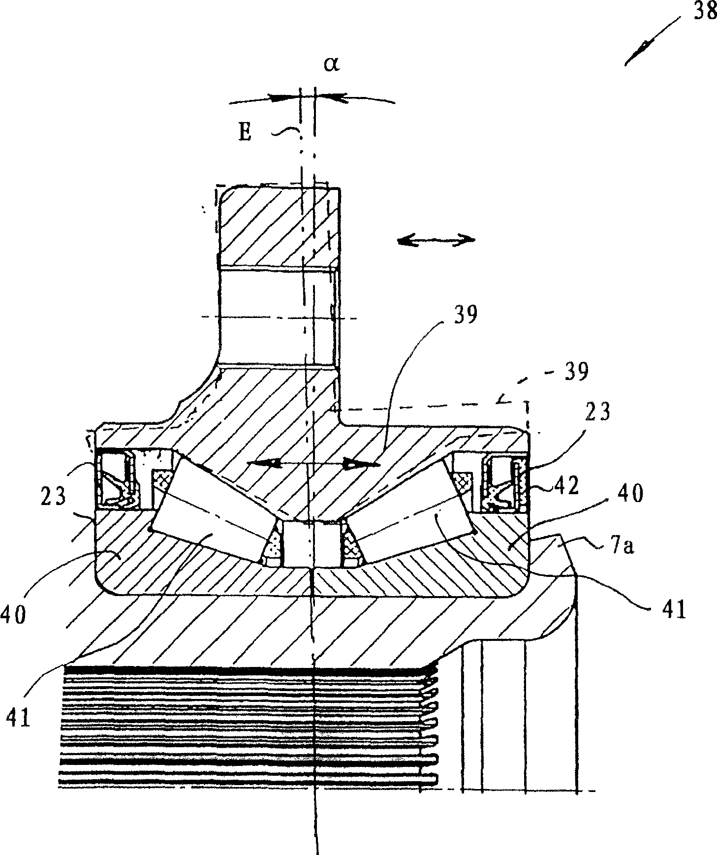
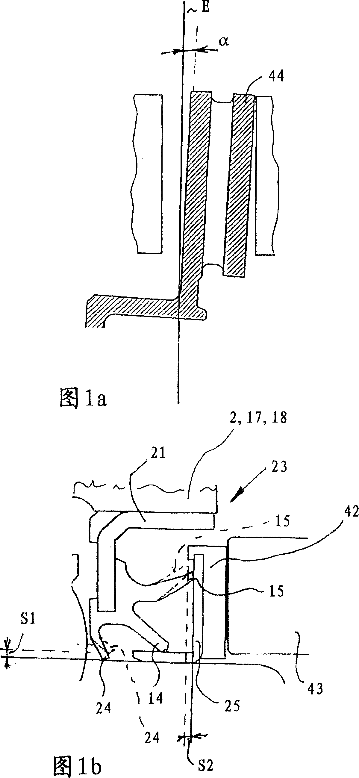
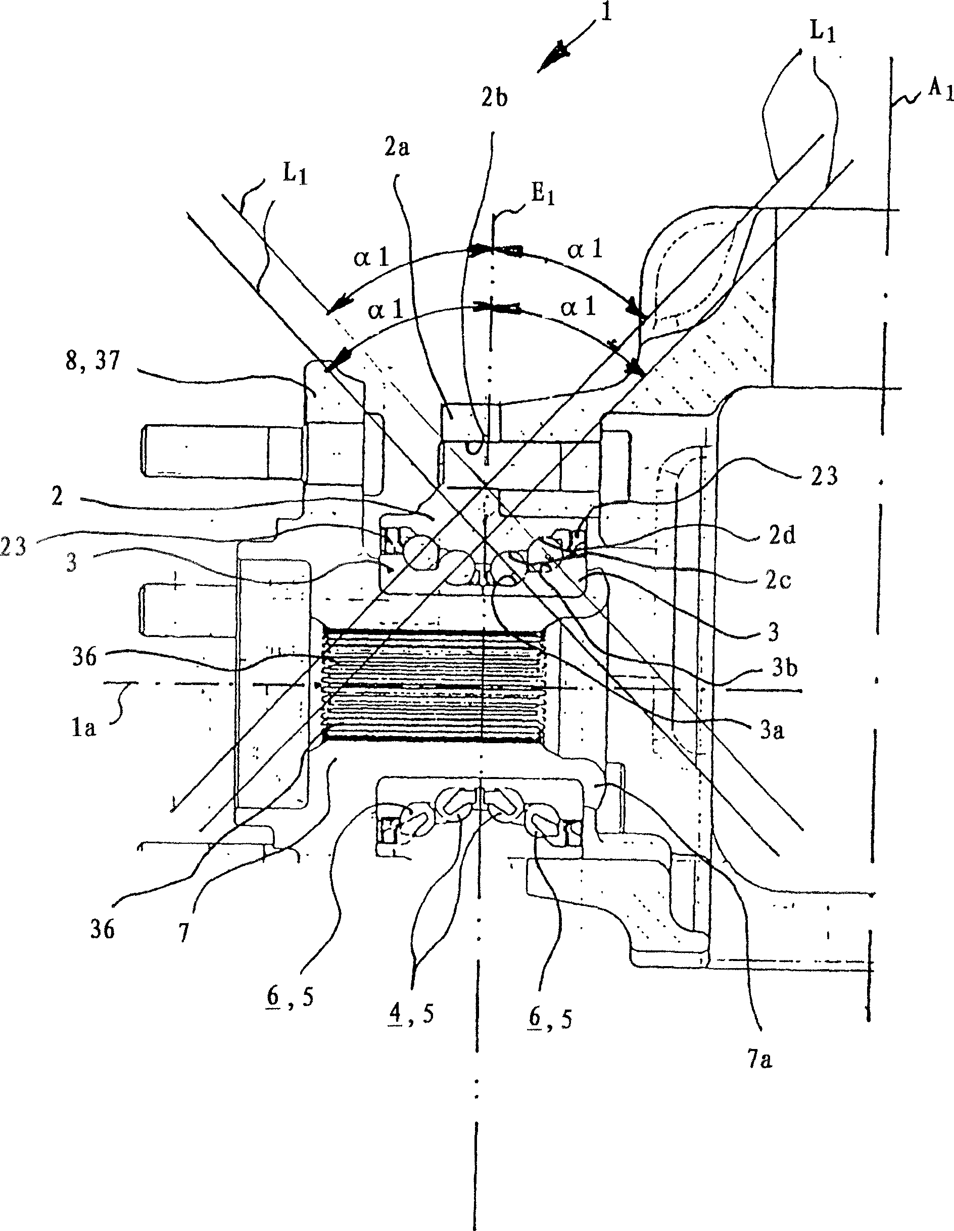
[0042] figure 1 This was previously described in detail in the "Background Art" section. The invention is suitable for wheel bearings on steered and non-steered wheels: figure 2 A wheel bearing unit 1 according to the invention is shown, which is arranged as a wheel bearing structure rotatable about an axis A and is driven by fine tooth splines 36 or similar form-locking elements. The wheel bearing unit 1 has an outer ring 2 , two inner rings 3 , two first rows 4 of balls 5 and two second rows 6 of balls 5 . In bearing radial plane E 1 A pair consisting of a first row 4 and a second row 6 is arranged on each side. Furthermore, the wheel bearing unit 1 has a flange body 7 which is equipped with a fastening element 8 in the form of a flange 37 . Wheel bolt 9 is fixedly installed in the flange 37.

[0043] The inner ring 3 is fixedly mounted on the flange body 7, and a bead-shaped flange 7a formed radially outward from the flange body 7 and pressed against an inner ring 3 c...


PUM


Abstract

A wheel bearing unit (1) is embodied in a four-rowed angular contact ball bearing form.

Description

technical field [0001] The invention relates to a wheel bearing unit of an angular contact ball bearing structure, which has at least two rows of balls in the first row surrounding the center line of the wheel bearing unit and two rows of balls in the second row parallel to the first row, one of which is formed by the second row of balls. A first pair consisting of one of the first columns and one of the second columns and a second pair consisting of one of the first columns and one of the second columns are mounted oppositely. Background technique [0002] A wheel bearing unit of this type is shown in GB 206,606. Such wheel bearing units are no longer adapted to the requirements of modern automobiles, especially when the wheel bearings are mounted on the automobile. Up to the moment when the present invention is made, professionals have no choice for wheel bearings on vehicles with medium and heavy loads. Tapered Roller Bearings. The advantage of using tapered roller bear...

Claims


Application Information

Patent Timeline
Patent Type & Authority Applications(China)
IPC IPC(8): F16C19/18B60B27/00F16C19/56G01P3/44
CPCF16C2326/02B60B27/00G01P3/443F16C19/505F16C19/182F16C19/184F16C2240/80F16C19/181F16C2240/34F16C19/18F16C19/56G01P3/42
Inventor P·尼布林H·霍夫曼D·德路盖J·海姆D·艾尔格特
Owner SCHAEFFLER TECH AG & CO KG
Learn More