Dry stack insulated building blocks

a technology of building blocks and stacks, applied in the direction of walls, constructions, building components, etc., can solve the problems of unreachable widespread use, inability to achieve widespread use, so as to reduce the misalignment or skewing of individual blocks, improve the shear strength and lateral strength of the standing wall, and facilitate the effect of creation

Inactive Publication Date: 2008-03-13
BRISTOL SYST INT
View PDF14 Cites 20 Cited by
  • Summary
  • Abstract
  • Description
  • Claims
  • Application Information

AI Technical Summary

Benefits of technology

[0026]Since dry stacked blocks employed in the erection of a standing wall are preferably coated, after erection of the wall, with a surface bond of cementious material, the block gap between blocks, as described above, will readily accept the surface bond of cementious material to provide a strong gapless interlock and enhance the shear strength and lateral strength of the standing wall. The surface bond can also provide the additional benefits of obscuring vertical, longitudinal and lateral variations in the alignment of the blocks in running courses and variations between adjacent courses.
[0027]Cores may be optionally provided with a pair of nodes or spurs on the top thereof and complementary recesses on the bottom thereof, which coact with one another to create an interlock when a structure is assembled. When blocks with cores inserted therein are laid in running courses, each spur will matingly interlock with a complementary recess. The interlocking of the several spurs with their corresponding recesses reduces the misalignment or skewing of individual blocks. Further, the interlocking of the spurs and recesses complements the stabilizing action of cores which extends from the open cells in one block into the contiguous open cell in the block adjacent thereto.
[0028]When local building codes or structural design requirements dictate that there be continuous vertical grout columns spaced along the running length of the wall, such a column is readily created by selectively omitting second or third cell cores in a vertically aligned series of short cells to create a continuous vertical void in the standing wall so erected. Thereafter one or more vertically extending reinforcing bars can be readily placed within the void and grouted in place to form a grout column. Likewise horizontal bond beams can be readily formed by omitting all second and third cell cores from a given running course of block, laying one or more horizontally-extending reinforcing bars in the curved notch bottom of the several intermediate transverse webs and thereafter filling the void remaining with grout. Preferably the first cell cores are also omitted from the same running course and one or more reinforcing bars are laid in the curved notch bottom of the several end transverse webs so as to extend across several first cells and thereafter filling the void remaining with grout. Additional horizontal bars can also be installed in a bond beam by running them through the second and third cells of a running course and through the first cells of a running course after partial filling of the cells of the course with grout.

Problems solved by technology

Dry stack block construction, masonry block construction without the use of mortar between adjacent block, has not achieved widespread use to date.
The inherent difficulty in manufacturing the dry stack block and the cell cores disclosed by Johnson '964 and Johnson '782 to precise dimensions, the variability, albeit lesser, in the dimensions of the cell cores, and the compressibility of the cell cores, albeit slight but variable depending on the density of the cell core, of the cell cores, provides for inadequate and inconsistent alignment and leveling of the block courses.
The experience of the present inventors has further led them to conclude that the transfer of vertical load from one course to another, during construction or thereafter, through the cell cores, is undesirable.
The foregoing limitations of the block, the block wall, and the method of Johnson '964 and Johnson '782 appear to be due primarily to lack of dimensional uniformity of the block, and variations in the dimensions and density of the cell cores.
Another particular problem noted with the dry stack block of Johnson '964 and Johnson '782 is that crumbing inherently occurs in the block manufacturing process causing crumbing to be deposited in and cemented in the notch bottom (“crotch”) of web notches in the block intended to receive the ears of the insulating, aligning, and leveling cell cores.
This causes the ears of the cell cores to fit poorly in the corresponding block web notches, further inhibiting the intended aligning and leveling function of the cell cores.

Method used


Image

  • Dry stack insulated building blocks
  • Dry stack insulated building blocks
  • Dry stack insulated building blocks

Examples


Embodiment Construction

[0059]While the terminology used in this application is standard within the art, the following definitions of certain terms are provided to assure clarity. Units, prefixes, and symbols may be denoted in their SI accepted form. Numeric ranges recited herein are inclusive of the numbers defining the range and include and are supportive of each integer within the defined range. Unless otherwise noted, the terms “a” or “an” are to be construed as meaning “at least one of.” The section headings used herein are for organizational purposes only and are not to be construed as limiting the subject matter described. All documents, or portions of documents, cited in this application, including but not limited to patents, patent applications, articles, books, and treatises, are hereby expressly incorporated by reference in their entirety for any purpose.

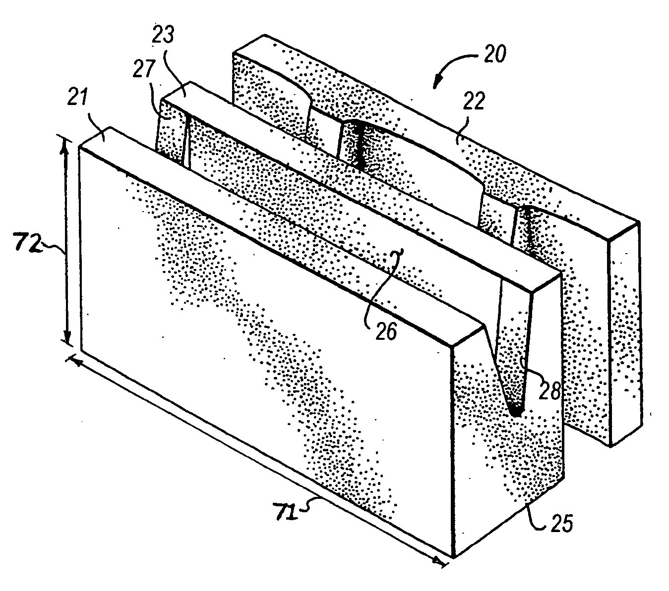
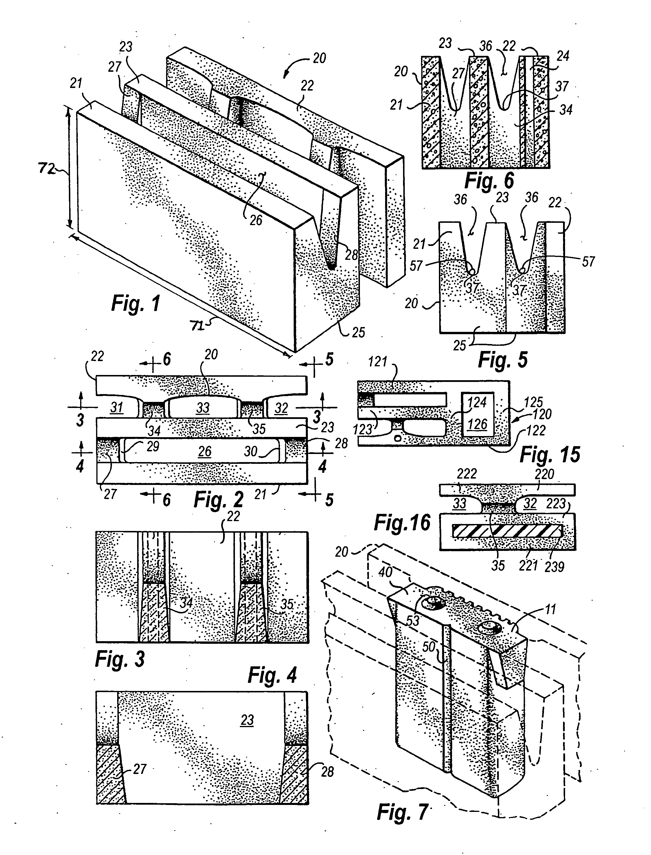
[0060]Referring first to FIGS. 1-6, a preferred embodiment of a dry stack construction block 20 is shown which comprises a first and a second s...


PUM


Abstract

An improved dry stack insulated building block and block wall system, the block having a first and a second side wall, a central web interposed between the side walls, a pair of end transverse webs, and a pair of intermediate transverse webs. The side walls, central web, and transverse webs define a first, a second, and a third cell. A first cell core, second cell core, and a pair of third cell cores of insulative material are inserted in the respective cells. The cell cores have trapezoidal shaped ear members which matingly fit in notches in the transverse webs, the trapezoidal shaped ear members providing for the creation of a notch gap between the base of the ear members and the notch bottom of the respective notches, thereby accommodating crumbing in the notch bottom.

Description

TECHNICAL FIELD OF THE INVENTION[0001]The present invention relates to dry stack construction blocks, i.e., blocks that may be stacked in running courses to erect a free-standing wall without the use of mortar. More particularly, the present invention relates to dry stack construction blocks with insulation inserts.BACKGROUND OF THE INVENTION[0002]The use of masonry blocks in the construction industry has been widespread for many years. Masonry blocks are constructed of various materials, lightweight concrete being the most prevalent. Various designs of blocks have also been utilized, many attempting to minimize the weight of the block while preserving as much structural strength as possible. Common block designs incorporate exterior walls connected by webs of various designs, creating interior cores of air space. In addition to reducing the weight of the block, the air space provides for decreasing the overall thermal conductivity of the block. Insulation inserts are also used in t...

Claims


Application Information

Patent Timeline
Patent Type & Authority Applications(United States)
IPC IPC(8): E04B1/74
CPCE04B2/52E04B2/8629E04C1/41E04B2002/8676E04B2002/0293
Inventor WESTMORELAND, AUSTIN P.WESTMORELAND, SHANE A.WESTMORELAND, WYNN L.
Owner BRISTOL SYST INT
Why Eureka
Try Eureka