Surface light source unit and device using the unit

A surface light source and light source arrangement technology, applied to lighting and heating equipment, light sources, electric light sources, etc., can solve the problems of unsightly, difficult to manufacture, and difficult to uniformly arrange light-emitting components 20, so as to reduce unevenness and suppress image quality Reduced effect

Active Publication Date: 2006-12-20
TOHOKU DENSHI CO LTD
View PDF1 Cites 13 Cited by
  • Summary
  • Abstract
  • Description
  • Claims
  • Application Information

AI Technical Summary

Problems solved by technology

[0012] However, using the Figure 8 The layout shown, creates gaps in the peripheral area in the circle, and the space is wasted
Also, using the Figure 9 With the layout shown, the light emitting components 20 are made entirely at uniform angles in a particular direction, so that the emission of light in a particular direction is pronounced, not uniform and visually unsightly
In this way, with conventional lighting lamps and pilot lights, it is difficult to uniformly arrange the light emitting parts 20 such as on a circle and to manufacture a lamp in which the light emitting points are uniformly aligned and looks good.

Method used


Image

  • Surface light source unit and device using the unit
  • Surface light source unit and device using the unit
  • Surface light source unit and device using the unit

Examples


Embodiment 1

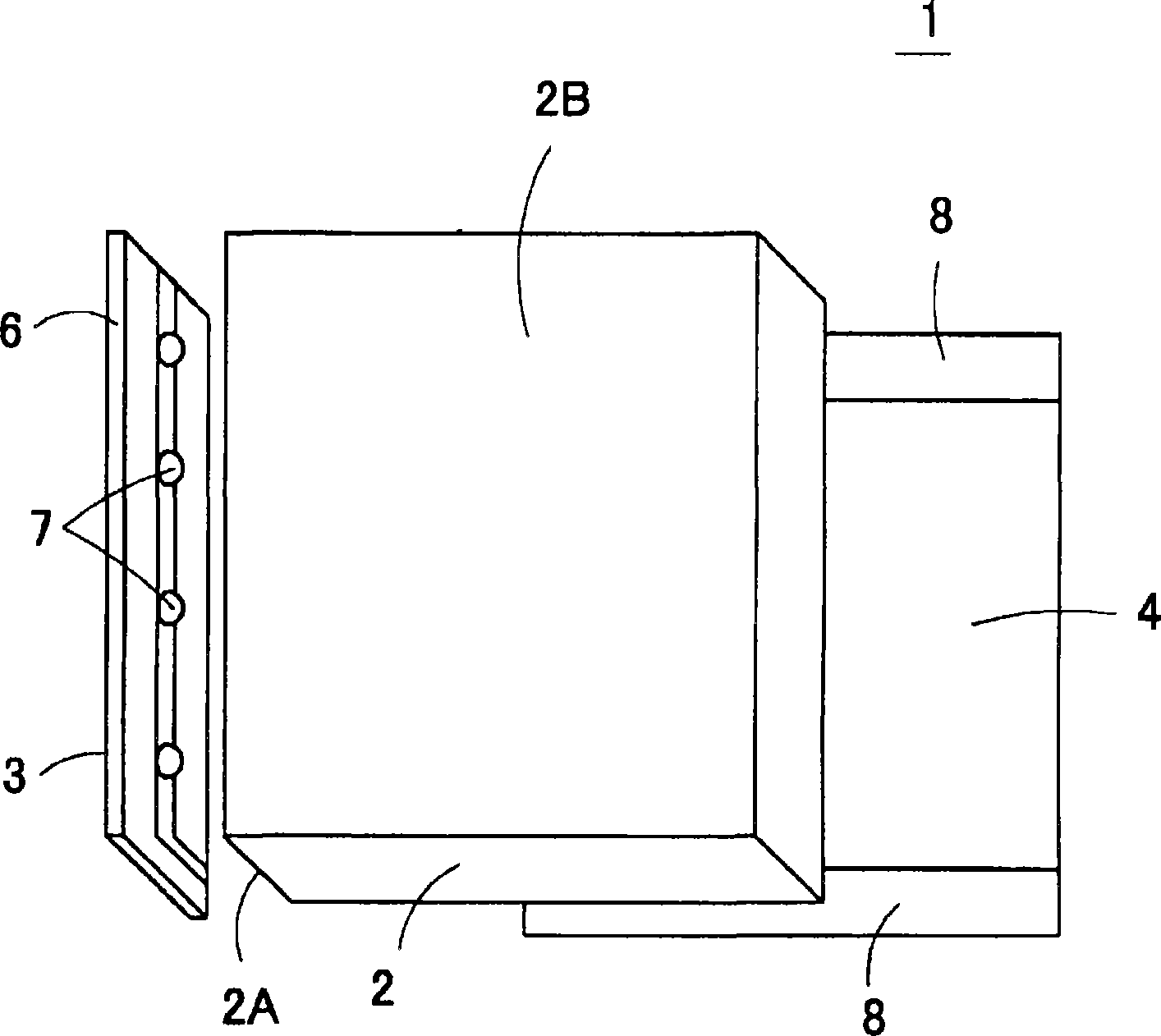
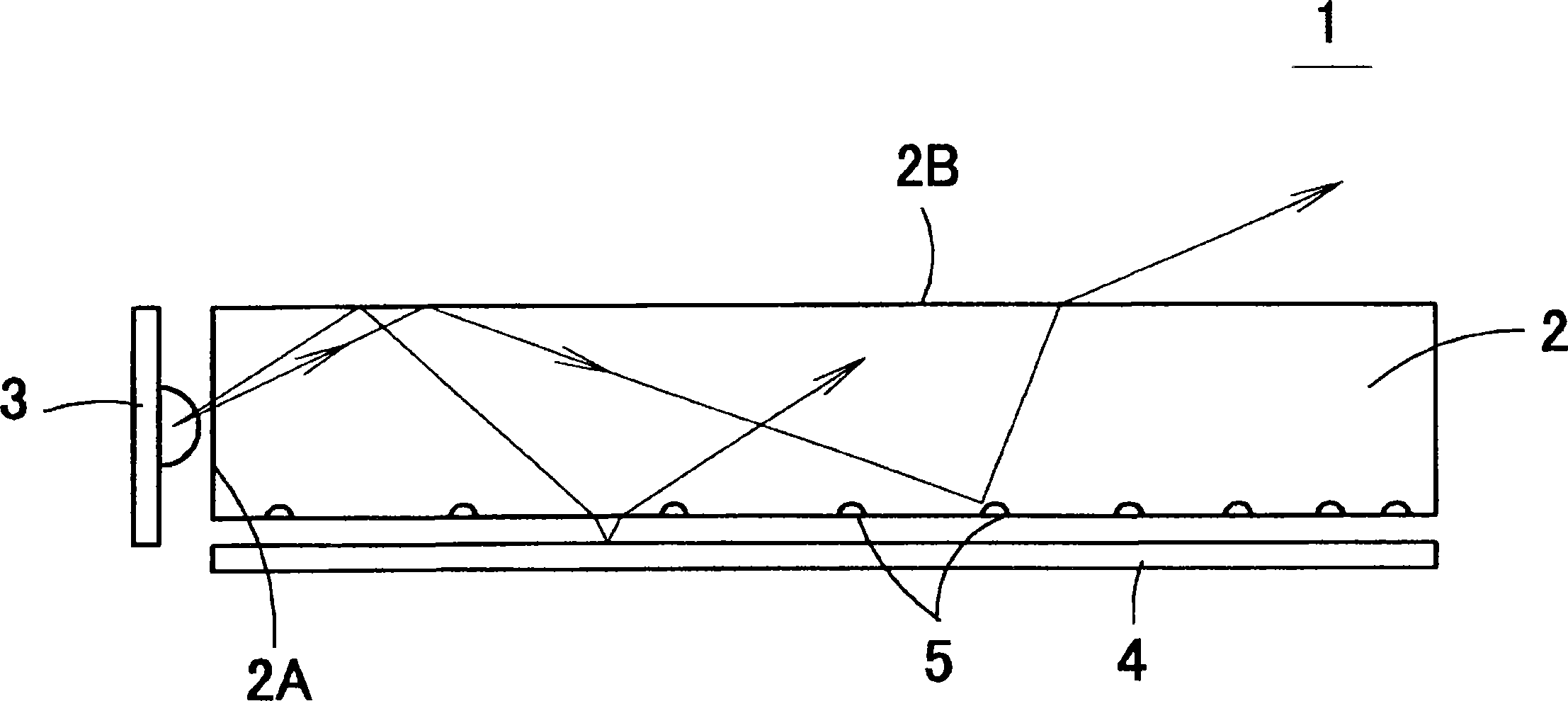
[0091] Figure 10 is an exploded perspective view showing the structure of the surface light source device 21 according to Embodiment 1 of the present invention, and Figure 11 is a sectional view showing the structure. The surface light source device 21 is used as a backlight of a liquid crystal display panel, and includes a light emitting part 22 in the form of a point light source, a light guide plate 23 and a reflective sheet 24 . The light emitting component 22 is embedded in a corner of the light guide plate 23 . The reflection sheet 24 is made of aluminum foil, white resin sheet, etc., and is disposed opposite to the back of the light guide plate 23 .

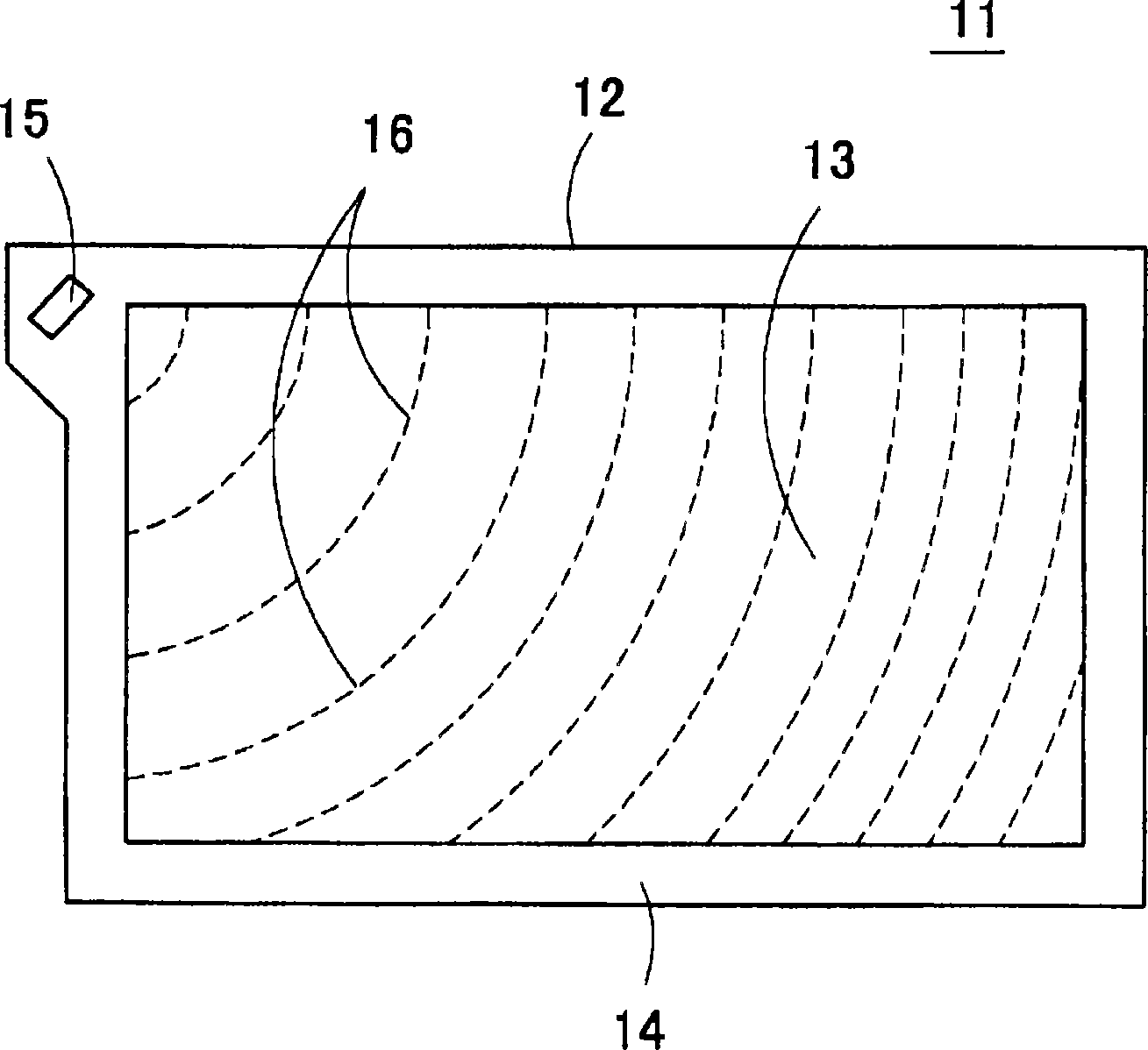
[0092] The light guide plate 23 is formed in a rectangular flat plate shape from a transparent resin having a high refractive index such as polycarbonate resin, acrylic resin, methacrylate resin, and glass. Figure 12is a schematic diagram showing the back side of the light guide plate 23 . The non-emission area 26 i...

Embodiment 2

[0136] Figure 30 is a schematic plan view showing a surface light source device according to Embodiment 2 of the present invention. The surface light source device includes a light emitting part 22 disposed centrally with respect to a side of the light guide plate 23 . The deflection pattern 34 is formed on the rear surface of the light guide plate 23 . In addition, although Figure 30 Only part of the deflection pattern 34 is shown, but the deflection pattern is formed in the entire surface emission area on the lower surface of the light guide plate 23 .

[0137] The pattern provided with the deflection pattern 34 in the surface light source device corresponds to that shown in Figure 23 Approximately 1 / 2 of the uniform basic pattern in the area, and the light emitting part 22 is arranged at the central point of the basic pattern.

Embodiment 3

[0139] Figure 31 is a sectional view showing a surface light source device 51 according to a third embodiment of the present invention. Figure 32 is a rear view showing the light guide plate 23 . The surface light source device is used as a lighting lamp for indoor lighting, photocopying lighting, etc., and includes: Figure 23 A uniform pattern shown in , which is formed on the entire back surface of the disc-shaped light guide plate 23; a tapered recess 52 for the light source formed in the center of the pattern; 52 in the light emitting component 22. Also, a reflective sheet 24 is provided on the entire back surface of the light guide plate 23 .

[0140] With this surface light source, the deflection pattern 34 can be uniformly arranged on the circular light guide plate 23 without intervals to achieve uniform light emission. This surface light source is


PUM


Abstract

Glaring and uneven luminance on a screen is limited when used for image displaying for a liquid crystal display unit or the like. A surface light source unit comprising a light emitting unit (22) using an LED or the like, and a light guide plate (23) for guiding light emitted from the light emitting unit (22) to spread it over the entire light output surface, wherein many deflection patterns (34) are provided on the rear surface of the light guide plate (23), and the deflection patterns (34) are used for reflecting a light in the light guide plate (23) to enable the light to be outputted from the light outputting surface of the light guide plate (23). When a polar coordinate using as the origin the center point set in the vicinity of one corner of the light guide plate is assumed, a location point (Rm, thetam) of a deflection pattern (34) is expressed in the following expressions (Ro > 0). Rm= Rm-1 + (1 / Rm-1) thetam= thetam-1 + 137.5 DEG.

Description

technical field [0001] The present invention relates to a surface light source device and an apparatus using the same, and more particularly to a surface light source device used as a backlight or a front light, an illumination device, etc. in an image display unit. Also, the present invention relates to an apparatus using the surface light source device. Background technique [0002] figure 1 and figure 2 are an exploded perspective view and a sectional view showing a surface light source device having a general structure. The surface light source device 1 is used as a backlight, and includes a light guide plate 2 that confines light, a light emitting part 3 and a reflection plate 4 . The light guide plate 2 is formed of a transparent resin such as polycarbonate resin, methacrylic resin, etc., and has a high refractive index. The diffusion pattern 5 is formed on the lower surface of the light guide plate 2 by letterpress processing, dot printing of diffusion and reflec...

Claims


Application Information

Patent Timeline
Patent Type & Authority Applications(China)
IPC IPC(8): F21S2/00F21V8/00F21Y101/02G09F9/00G02F1/13357G02B6/00F21S8/04G02F1/1335G09F13/18
CPCG02B6/0036G02B6/0061G02F1/1335
Inventor 篠原正幸广田和英
Owner TOHOKU DENSHI CO LTD
Why Eureka
Try Eureka