Sealed volumetric vane pump

A vane pump and volumetric technology, applied in the direction of rotary piston pumps, pumps, rotary piston machines, etc., can solve the problems of increasing manufacturing difficulty and use cost, reducing the effective power of volumetric vane pumps, etc., and achieving the goal of reducing machining accuracy Requirements, cost-effective manufacturing

Inactive Publication Date: 2006-12-27
丁桂秋 +2
View PDF0 Cites 6 Cited by
  • Summary
  • Abstract
  • Description
  • Claims
  • Application Information

AI Technical Summary

Problems solved by technology

Due to the unavoidable dimensional errors in manufacturing and the wear of positive displacement vane pumps during operation, the leakage of fluid from the high-pressure area to the low-pressure area is inevitable between the rotor and the end cover of the positive displacement vane pump, and between the rotor and the stator. Therefore, the effective power of the displacement vane pump is reduced, and the difficulty of manufacturing and the cost of use are increased.

Method used


Image

  • Sealed volumetric vane pump
  • Sealed volumetric vane pump
  • Sealed volumetric vane pump

Examples


Embodiment 1

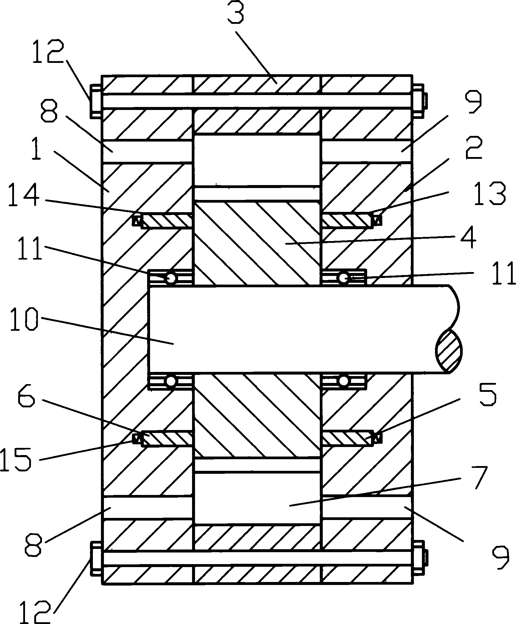
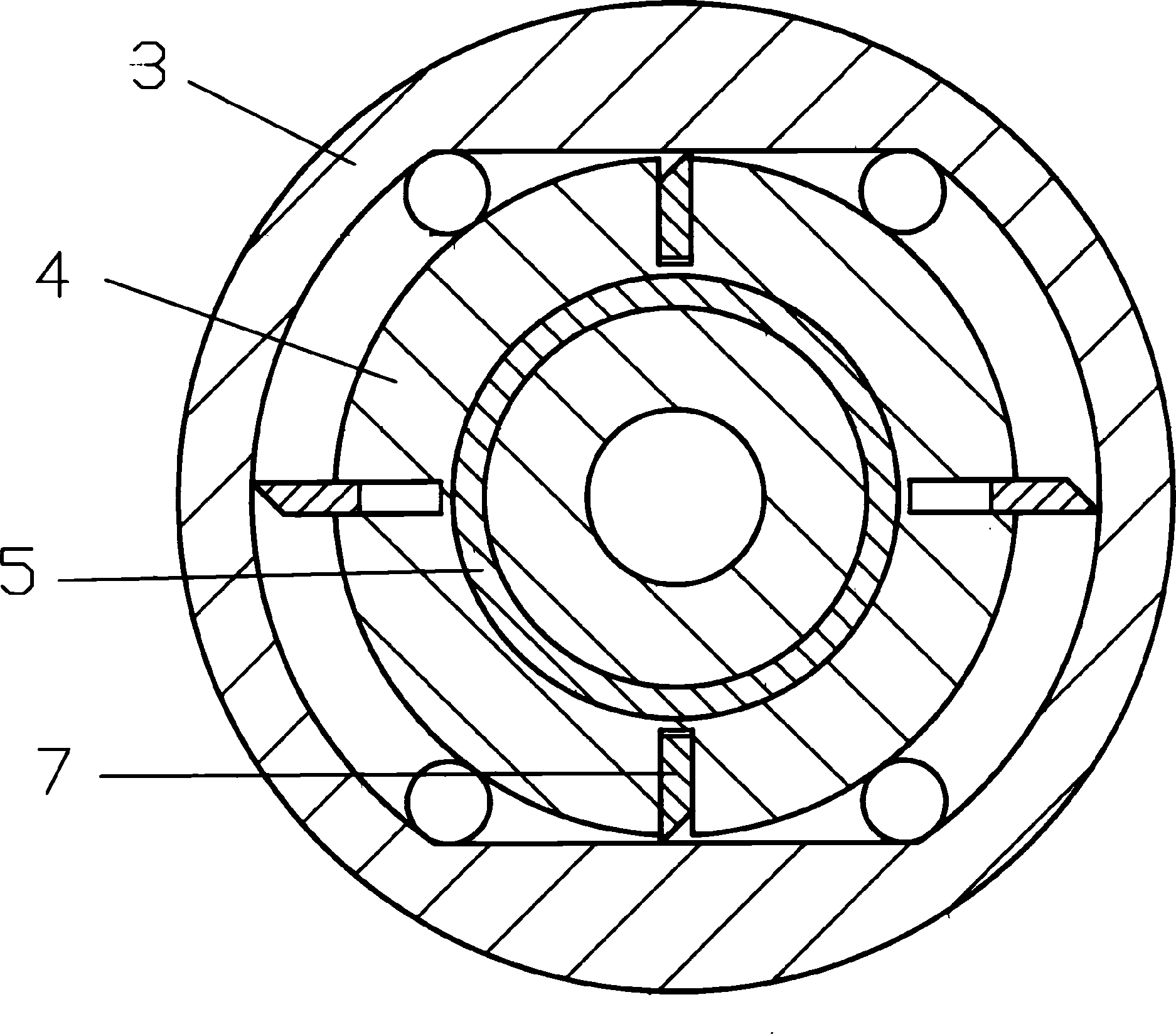
[0013] The sealed displacement vane pump of the present embodiment is as figure 1 , 2 As shown, 1 and 2 in the figure represent both end covers; 3 represents the stator; 4 represents the rotor; 5 and 6 represent two sealing rings; 7 represents the sliding vane; 8 represents two oil inlet holes; 9 represents two oil discharge holes 10 represents the rotating shaft; 11 represents two bearings; 12 represents two bolts fixedly connecting the two end caps; 13 and 14 represent the sealing ring grooves on the inside of the two end caps; 15 represents the spring.

[0014] The rotor 4 driven by the shaft 10 is installed in the pump cavity formed by the end covers 1 , 2 and the stator 3 fixedly connected by bolts 12 . Blades 7 that can slide are housed in the radial slots of the rotor 4 . A seal ring 5,6 that can slide axially in the groove is respectively housed in the seal ring groove 13,14 of the end cover 1,2 inner side by means of oil pressure or spring action. The shaft 10 is s...

Embodiment 2

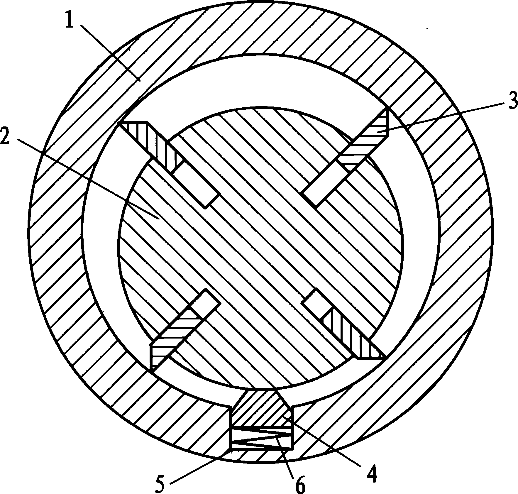
[0017] The sealed displacement vane pump of the present embodiment is as Figure three shown. In the figure, 1 represents the stator with a sealing plate groove processed on the inner surface; 2 represents the rotor; 3 represents the blade installed in the blade groove of the rotor 2; 4 represents the sealing plate that can slide radially in the sealing plate groove; 5 represents the sealing plate Groove; 6 represents spring.

[0018] When the rotor 2 rotates with the vane 3, the tip of the vane 3 touches the inner surface of the stator to start pumping oil, and at this time, a multi-directional oil pressure difference is formed in the pump chamber. Especially, there is a tendency to leak from the high-pressure area to the low-pressure area on the outer surface of the rotor 2 and the inner surface of the stator 1, but the inner end of the sealing plate 4 is tightly attached to the outer surface of the rotor 2 under the action of elastic force or oil pressure up, thereby bloc...


PUM


Abstract

The invention relates to a structure improvement of volumetric blade pump, which comprises a pump chamber formed by stator and end cover, and a rotor mounted inside the pump chamber, wherein the radial groove of rotor is mounted with blades that sliding matched; the inner side of the stator has radial sealing groove mounted with sealing blade that radial sliding to contact with rotor; the inner side of two end covers are made with sealing annular groove mounted with sealing ring that axially sliding to contact the rotor. Therefore, the invention can avoid pressure liquid leaked via the space between blade and stator, or avoid pressure liquid leaked via the space of bearings, to reduce the accuracy demand.

Description

technical field [0001] The invention relates to a pump, more specifically a displacement vane pump, belonging to the field of fluid delivery facilities. Background technique [0002] At present, the commonly used volumetric vane pumps have single-acting and double-acting structural forms. Due to the unavoidable dimensional errors in manufacturing and the wear of positive displacement vane pumps during operation, the leakage of fluid from the high-pressure area to the low-pressure area is inevitable between the rotor and the end cover of the positive displacement vane pump, and between the rotor and the stator. Therefore, the effective power of the positive displacement vane pump is reduced, and the manufacturing difficulty and use cost are increased. Contents of the invention [0003] The technical problem to be solved by the present invention is to propose a sealed positive displacement vane pump that can avoid fluid leakage and reduce the original processing precision r...

Claims


Application Information

Patent Timeline
Patent Type & Authority Applications(China)
IPC IPC(8): F04C2/344
Inventor 丁桂秋丁勇丁霞
Owner 丁桂秋
Why Eureka
Try Eureka