Light tube wire structure

A wire and lamp technology, applied in the field of lamp wire structure, can solve problems such as deformation or fracture

Inactive Publication Date: 2006-12-27
AU OPTRONICS CORP
View PDF0 Cites 0 Cited by
  • Summary
  • Abstract
  • Description
  • Claims
  • Application Information

AI Technical Summary

Problems solved by technology

Therefore, under the above-mentioned bending or pulling, under the same degree of destructive stress, the low-voltage wire 11 and the higher-voltage wire 10 are more likely to be deformed or broken.

Method used


Image

  • Light tube wire structure
  • Light tube wire structure
  • Light tube wire structure

Examples


Embodiment Construction

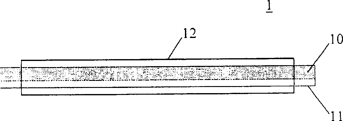
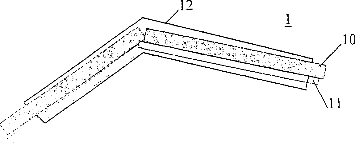
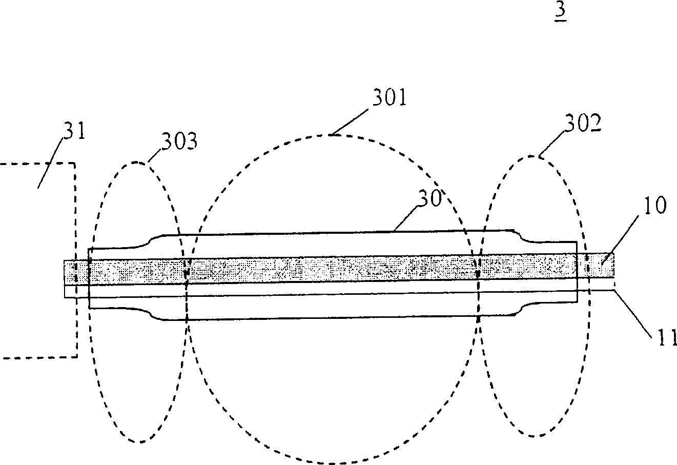
[0035] Please refer to image 3 It is a schematic diagram of an embodiment of the lamp tube wire structure of the present invention. exist image 3 Among them, the lamp tube wire structure 3 includes a high-voltage wire 10 , a low-voltage wire 11 and a first heat-shrinkable sleeve 30 . Wherein, the high voltage wire 10 can be a copper wire, and is used to transmit a high voltage value to a lamp group 31 . The low voltage wire 10 can also be a copper wire, and is used to transmit a low voltage value to the lamp group 31 . In this embodiment, the high-voltage wire 10 transmits a larger voltage value than the low-voltage wire 11 , and the diameter of the wire is generally larger. In addition, the first heat-shrinkable sleeve 30 has a first end 302, a second end 303, and an intermediate region 301 between the first end 302 and the second end 303, for covering the high-voltage wire 10 and the low-voltage wire 10. The wire 11, and the middle area 301 thereof is not baked, so tha...


PUM


Abstract

The invention relates to a wire structure of tube, used in plane display panel, wherein said invention at least comprises one high-voltage wire, at least one low-voltage wire and first heat constriction sleeve; the first heat constriction sleeve packs the high-voltage wire and the low-voltage wire, while it has the first, second ends and one middle section between the first and second ends; by heating the first and second ends, the middle section and the packed wires have movable space. The invention can effectively strengthen the anti-bend ability of tube wire structure.

Description

technical field [0001] The invention relates to a lamp tube wire structure, in particular to the technical field of heating the two ends of the heat-shrinkable sleeve in the wire structure. Background technique [0002] In the prior art, the light source required by the flat panel display device usually comes from a backlight module. The light tube group in the backlight module is naturally the provider of the light source. Here, the lamp group usually transmits and supplies the required power from the outside through a lamp wire. [0003] Please refer to figure 1 It is a schematic diagram of lamp tube wires in the prior art. exist figure 1 Among them, the lamp tube wire 1 includes at least one high-voltage wire 10 , at least one low-voltage wire 11 and a protective bundle tube 12 . Here, the high-voltage wire 10 is used to conduct a higher-voltage power source from the outside and usually uses a thicker copper wire. The low-voltage wire 11 is used to conduct a low-vol...

Claims


Application Information

Patent Timeline
Patent Type & Authority Applications(China)
IPC IPC(8): F21V15/00F21V37/00
Inventor 陈信利郑美俊
Owner AU OPTRONICS CORP
Why Eureka
Try Eureka