Continuously variable transmission

A continuously variable speed change device, the technology of speed change device, applied in the direction of hoisting device, transmission device, transmission device control, etc., to achieve the effect of accurately controllable and predictable changing speed, economical production and operation

Active Publication Date: 2006-12-27
ROBERT BOSCH GMBH
View PDF3 Cites 4 Cited by
  • Summary
  • Abstract
  • Description
  • Claims
  • Application Information

AI Technical Summary

Problems solved by technology

However, as already noted, the minimum primary clamping force Kp required to transmit the provided torque corresponds to the required minimum secondary clamping force Ks, so that the latter fits the primary clamping force Kp DV Insufficient, and the drive belt will slip relative to the primary pulley

Method used


Image

  • Continuously variable transmission
  • Continuously variable transmission
  • Continuously variable transmission

Examples


Embodiment Construction

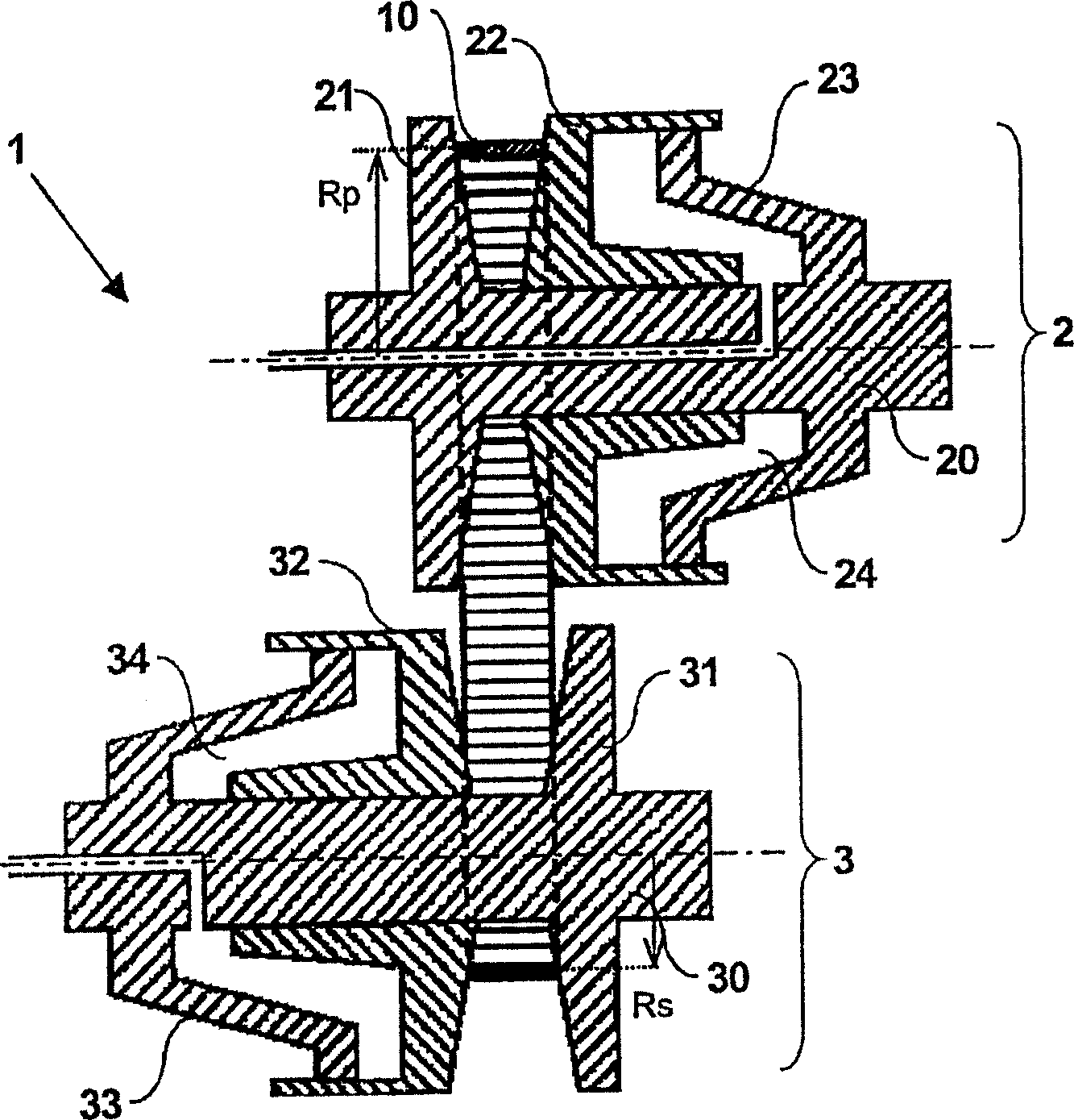
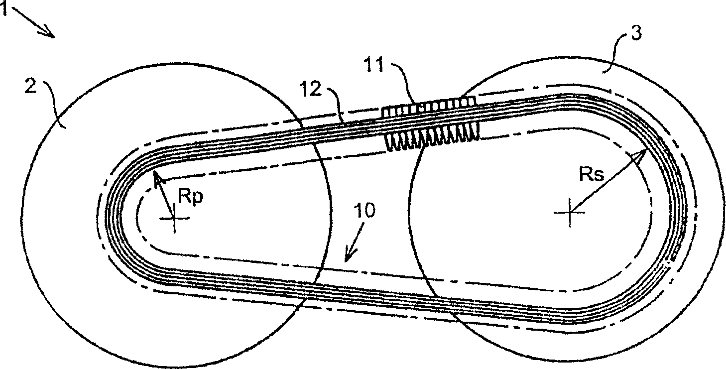
[0046] figure 1 A cross-sectional view through a continuously variable transmission 1 according to the prior art is schematically depicted. A known speed change device 1 includes a primary pulley 2 that can be driven by an engine (not shown) with two forces Tp and a secondary pulley 3 that can drive a load with a pair of forces Ts (not shown). show). The pulleys 2 and 3 are provided with pulley disks 21 and 31 fixed to respective pulley shafts 20 , 30 and with pulley disks 22 , 32 displaceable relative to said shafts 20 , 30 in the axial direction. The drive belt 10 , more specifically the pressure belt 10 , is clamped between pulley discs 21 , 22 , 31 , 32 so as to be able to be driven between the two shafts 20 , 30 by means of frictional mechanical energy. In this case, the axially directed force with which the drive belt 10 uses for each The pulleys 2, 3 are clamped in place, said forces hereinafter referred to as primary clamping force Kp and secondary clamping force Ks...


PUM


Abstract

Continuously variable transmission (1) for motor vehicles, provided with a primary pulley (2) and a secondary pulley (3), around which there is arranged a drive belt (10), which is clamped between two conical pulley disks of the primary pulley (2) with a primary claming force and between two conical pulley disks of the secondary pulley (3) with a secondary clamping force, wherein, as a result of a contact angle of at least one of the pulley disks of the respective pulleys (2; 3) with the drive belt (10) being adapted, and at least in the largest transmission ratio of the transmission (1), i.e. Low, a clamping force ratio between the primary clamping force and the secondary clamping force has a value in the range between 1 and the clamping force ratio in the smallest transmission ratio, i.e. Overdrive.

Description

technical field [0001] The invention relates to a continuously variable transmission according to the preamble of claim 1 . This type of transmission is well known and is used to transmit mechanical energy between the primary pulley and the secondary pulley of the transmission. It is possible for the transmission ratio of the transmission to vary continuously in a certain range, wherein a pair of rotational speeds is in The gear ratio transfers. As is well known, the drive belt is sandwiched between two pulley disks of each pulley, the pulley disks being substantially frusto-conical or conical in shape; in the present invention, the transmission ratio of a transmission is defined as the The ratio between the effective radial position of the drive belt and the effective radial position of the drive belt on the primary pulley, which positions may also be referred to as secondary and primary running radii, respectively. In order to be able to change these running radii and thus...

Claims


Application Information

Patent Timeline
Patent Type & Authority Applications(China)
IPC IPC(8): F16H61/00F16H55/56F16H61/662
CPCF16H55/56F16H61/66272F16H9/125F16H61/66F16H61/662F16H61/00
Inventor 阿德里安斯·约翰尼斯·威廉默斯·范德莱斯特阿尔耶恩·布兰兹玛约翰尼斯·赫拉尔杜斯·卢多维克斯·玛丽亚·范斯皮耶克
Owner ROBERT BOSCH GMBH
Why Eureka
Try Eureka