
Balanced self-stabilization type spatial motion positioning system

A space motion and positioning system technology, applied in general control systems, control/adjustment systems, instruments, etc., can solve the problems of narrow application area, large noise of inertial measurement unit, loss of flexible movement, etc., and achieve strong battery life and low power consumption. Low, work stable effect

Active Publication Date: 2021-04-30
ZHEJIANG UNIV
View PDF8 Cites 0 Cited by
  • Summary
  • Abstract
  • Description
  • Claims
  • Application Information

AI Technical Summary

Problems solved by technology

[0003] The Sahara pipeline detection device developed by Pure company abroad can be used for defect detection of pressurized water supply pipelines. Its communication cable restricts its movement distance and flexibility; and the cable-free pipeline robot is usually based on its own wheel odometer. Obtain the distance and posture of its own movement, but affected by its structure, it can only move in a simple straight pipeline, and cannot work in a pressurized pipeline, and its flexibility is greatly restricted; therefore, the spherical detection device is due to its The simple structure and small size have attracted widespread attention in the industry. The device moves in the tube and performs detection tasks through the promotion of water flow. It is a passive detection device, and the distance information of its movement is solved by its own inertial measurement unit. However, due to the large noise contained in the inertial measurement unit, the positioning strategy often cannot obtain accurate positioning results, and the device cannot move autonomously, making it lose the ability to move flexibly, and the application area is narrow

Method used


Image

  • Balanced self-stabilization type spatial motion positioning system
  • Balanced self-stabilization type spatial motion positioning system
  • Balanced self-stabilization type spatial motion positioning system

Examples


Embodiment Construction

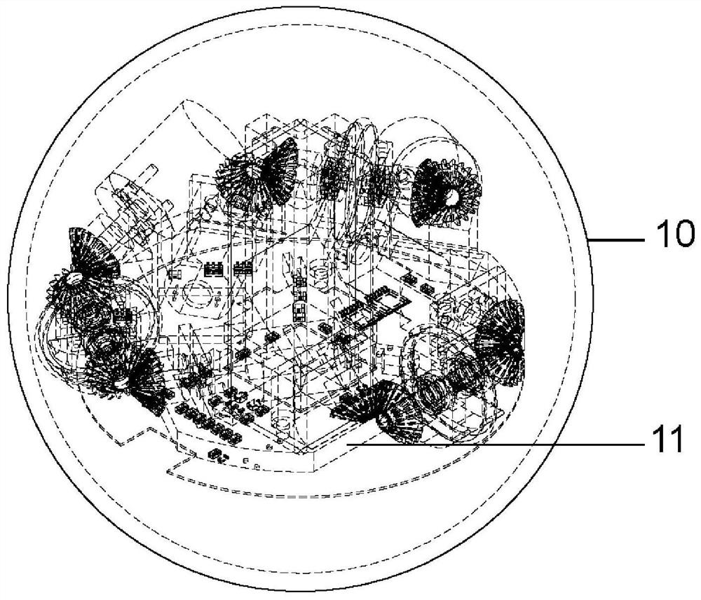
[0019] Such as figure 1 It is a perspective view of the overall structure of the balanced self-stabilizing space motion positioning system of the present invention. The space motion positioning system includes a spherical shell 10, an equilibrium state self-stabilizing mechanism 11, a balance platform, an integrated circuit board 9 and a power supply, and the equilibrium state self-stabilizing The mechanism 11 is arranged inside the spherical shell 10 and is fixedly connected with the balance platform 4 , the balance platform is fixedly connected with the integrated circuit board 9 , and the power supply is connected with the integrated circuit board 9 .

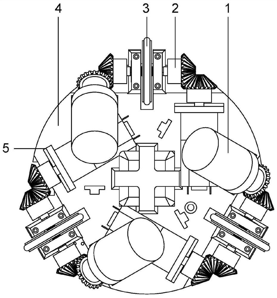
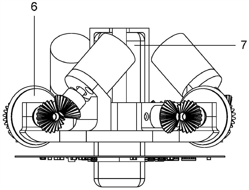
[0020] Such as Figure 2-4 It is a structural diagram of the internal equilibrium state self-stabilizing mechanism of the space motion positioning system of the present invention. The equilibrium state self-stabilizing mechanism 11 has three groups of driving and detecting units, and the three groups of driving and detecting...


PUM


Abstract

The invention discloses a balanced self-stabilization type spatial motion positioning system which comprises a spherical shell, a balance state self-stabilization mechanism, a balance table, an integrated circuit board and a power supply; the balance state self-stabilizing mechanism is arranged in the spherical shell and fixedly connected with the balance table, the balance table is fixedly connected with the integrated circuit board, and the power source is connected with the integrated circuit board; the balance state self-stabilization mechanism is provided with three sets of driving and detecting units, and the three sets of driving and detecting units are distributed around the circumference of the power source at equal intervals with the center of the balance state self-stabilization mechanism as a reference point. The spatial motion positioning system controls the attitude angle, the angular velocity, the angular acceleration, the rotating speed and the like, can calculate the motion condition and the motion track of the system according to the acquired data, can be used in the fields of map construction, exploration, robot positioning and the like, and has the advantages of stability, convenience, high efficiency and the like.

Description

technical field [0001] The invention belongs to the technical field of robot positioning, and in particular relates to a balanced self-stabilizing space motion positioning system. Background technique [0002] With the continuous development of science and technology, robots are increasingly used in various industries and environments. However, because many robots need to operate in closed and unknown environments, and these environments are relatively small, they cannot receive GPS signals or other signals for real-time positioning. For example, spherical pipeline robots usually need to perform various defect detection tasks (cracks, sags, etc.) or carry out various in-pipe operations (cleaning, welding, etc.) in buried pipelines. Position information is crucial for pipeline robots . The traditional pipeline robot positioning adopts the traction rope measurement method, that is, the distance of the robot’s movement is inferred by measuring how long the rope connected to t...

Claims


Application Information

Patent Timeline
Patent Type & Authority Applications(China)
IPC IPC(8): G05D1/08G05B19/042G01D21/02
CPCG05D1/08G05B19/042G01D21/02
Inventor 侯迪波袁帅喻洁张力肖耀黄平捷张光新张宏建
Owner ZHEJIANG UNIV
Learn More