
Pipe fitting support and thermal deformation compensation device for pipe fitting support

A compensation device and thermal deformation technology, applied in the direction of pipeline supports, pipes/pipe joints/fittings, mechanical equipment, etc., can solve problems such as large pipeline stress, affecting pipeline life and reliability, engine accidents, etc., to reduce Effect of thermal deformation stress

Active Publication Date: 2022-01-07
AECC COMML AIRCRAFT ENGINE CO LTD
View PDF20 Cites 0 Cited by
  • Summary
  • Abstract
  • Description
  • Claims
  • Application Information

AI Technical Summary

Problems solved by technology

During the operation of the engine, the pipeline will inevitably expand or shrink and deform due to temperature changes. Due to the existence of the clamp, the pipeline is restrained and cannot be freely deformed, which will cause a large stress in the pipeline and affect the pipeline. The life and reliability of the engine, under the severe working conditions of the engine, may lead to cracks, fractures and other failures, and even cause engine accidents, the consequences are very serious. Therefore, certain measures must be taken to compensate for the deformation of the pipeline and reduce the stress of the pipeline

Method used


Image

  • Pipe fitting support and thermal deformation compensation device for pipe fitting support
  • Pipe fitting support and thermal deformation compensation device for pipe fitting support
  • Pipe fitting support and thermal deformation compensation device for pipe fitting support

Examples


Embodiment Construction

[0022] The present invention will be further described below in conjunction with specific embodiment and accompanying drawing, set forth more details in the following description so as to fully understand the present invention, but the present invention can obviously be implemented in many other ways different from this description, Those skilled in the art can make similar promotions and deductions based on actual application situations without violating the connotation of the present invention, so the content of this specific embodiment should not limit the protection scope of the present invention.

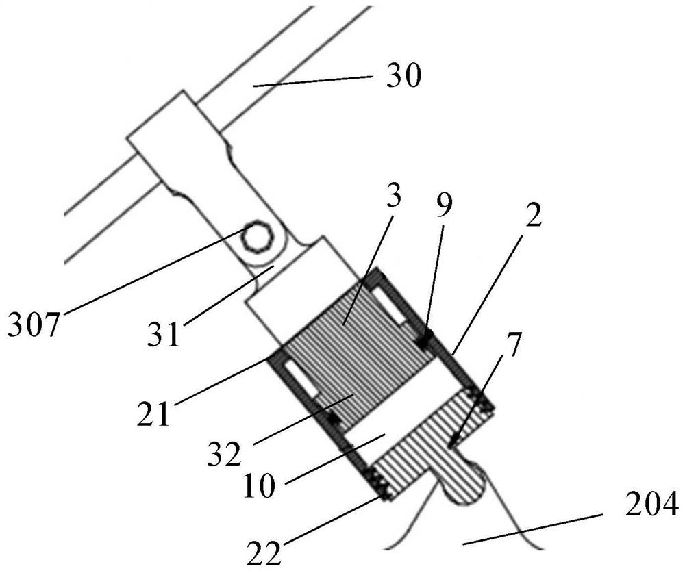
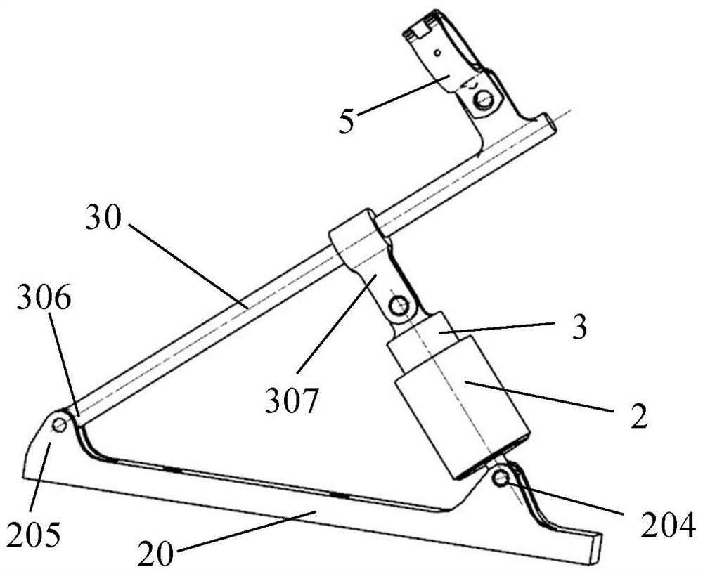
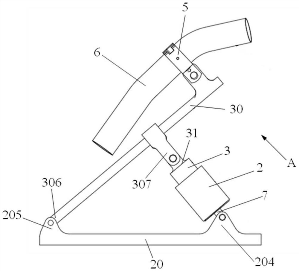
[0023] A pipe fitting bracket and a thermal deformation compensating device used for the pipe fitting bracket can effectively solve the problem that the existing pipeline clip assembly cannot compensate for the deformation of the pipeline caused by temperature changes when it is fixed. like figure 1 As shown, the thermal deformation compensation device includes a sleeve 2. The ...


PUM


Abstract

The invention provides a pipe fitting support and a thermal deformation compensation device for the pipe fitting support. The thermal deformation compensation device comprises a sleeve, wherein the sleeve is provided with a first end and a second end, and the second end is provided with a micro air gap communicating with the outside of the sleeve and a third connecting part; and a piston rod which comprises an inner end and an outer end, wherein the inner end is located in the sleeve and is in sealing and sliding fit with the inner wall of the sleeve, and the outer end extends out of the first end and is located on the outer side of the sleeve. An air chamber is formed between the inner end of the piston rod and the second end of the sleeve, the micro air gap allows air in the air chamber to expand when heated or contract when cooled to form pressure difference with air pressure outside the sleeve, the piston rod is pushed outwards or inwards through the pressure difference, and the outer end of the piston rod and the third connecting part are used for being connected with two parts capable of moving relatively. Through stretching of the piston rod in the sleeve, pipeline thermal deformation can be effectively offset, and pipeline stress is reduced.

Description

technical field [0001] The invention relates to the technical field of assembly, connection and fixation, in particular to the fixation and support of heat-deformed pipelines. Background technique [0002] The pipeline is equivalent to the blood vessel of the engine, which connects the components of the engine, between accessories, between components and accessories, and between the engine and the aircraft, and transports the fluid medium specified by each to realize engine operation, control, manipulation and other functions. During the operation of the engine, the pipeline is in a harsh environment and needs to withstand vibration, temperature shock, and even physical collision. Therefore, the pipeline must be fixed with clamps to improve rigidity and strength to ensure reliable connection and fixation. This is a stable and reliable engine. necessary conditions for work. Since the ambient temperature of the pipeline changes greatly, and the temperature range can reach sev...

Claims


Application Information

Patent Timeline
Patent Type & Authority Applications(China)
IPC IPC(8): F16L3/217F16L3/10
CPCF16L3/217F16L3/10
Inventor 王光强李睿徐联杰
Owner AECC COMML AIRCRAFT ENGINE CO LTD
Learn More