Thermoelectric devices and applications for the same

A kind of thermoelectric device, thermoelectric technology, applied in thermoelectric device components, thermoelectric device junction lead-out materials, thermoelectric devices that only use Peltier or Seebeck effect, etc., can solve the problem that the distance is small and has not been successfully configured to take advantage of temperature changes And other issues

Inactive Publication Date: 2007-01-03
BATTELLE MEMORIAL INST
View PDF1 Cites 33 Cited by
  • Summary
  • Abstract
  • Description
  • Claims
  • Application Information

AI Technical Summary

Problems solved by technology

However, since the distance across conventional thermoelectric devices is typically small, none has been successfully configured to exploit, for example, temperature changes between the ground below it and the air above it.

Method used


Image

  • Thermoelectric devices and applications for the same
  • Thermoelectric devices and applications for the same
  • Thermoelectric devices and applications for the same

Examples


Embodiment Construction

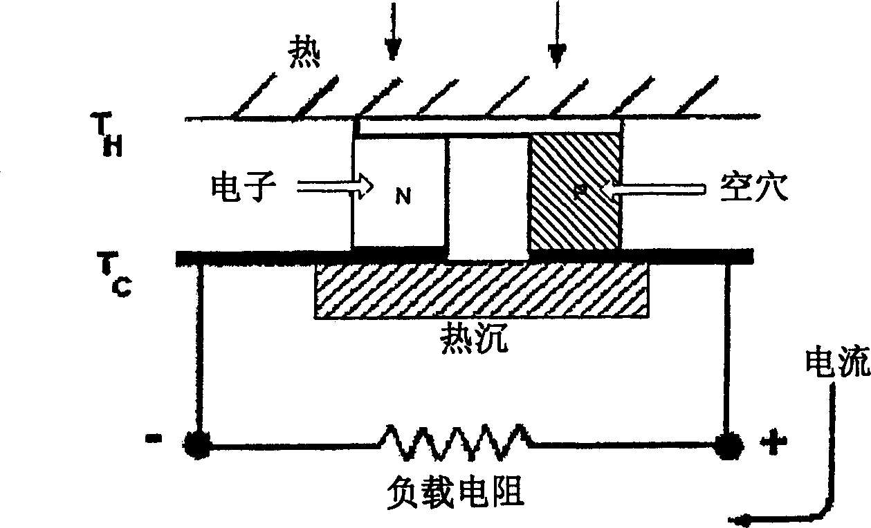
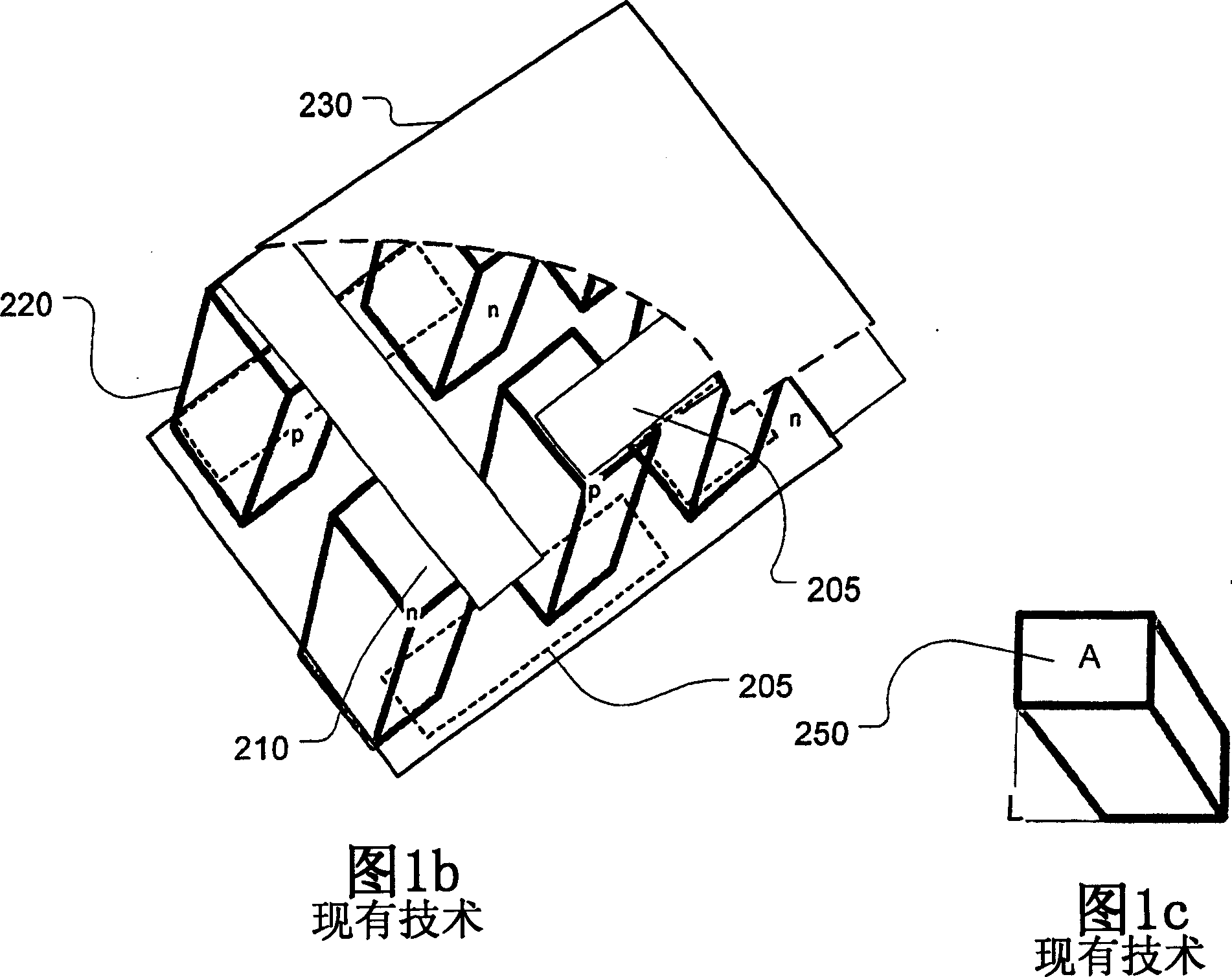
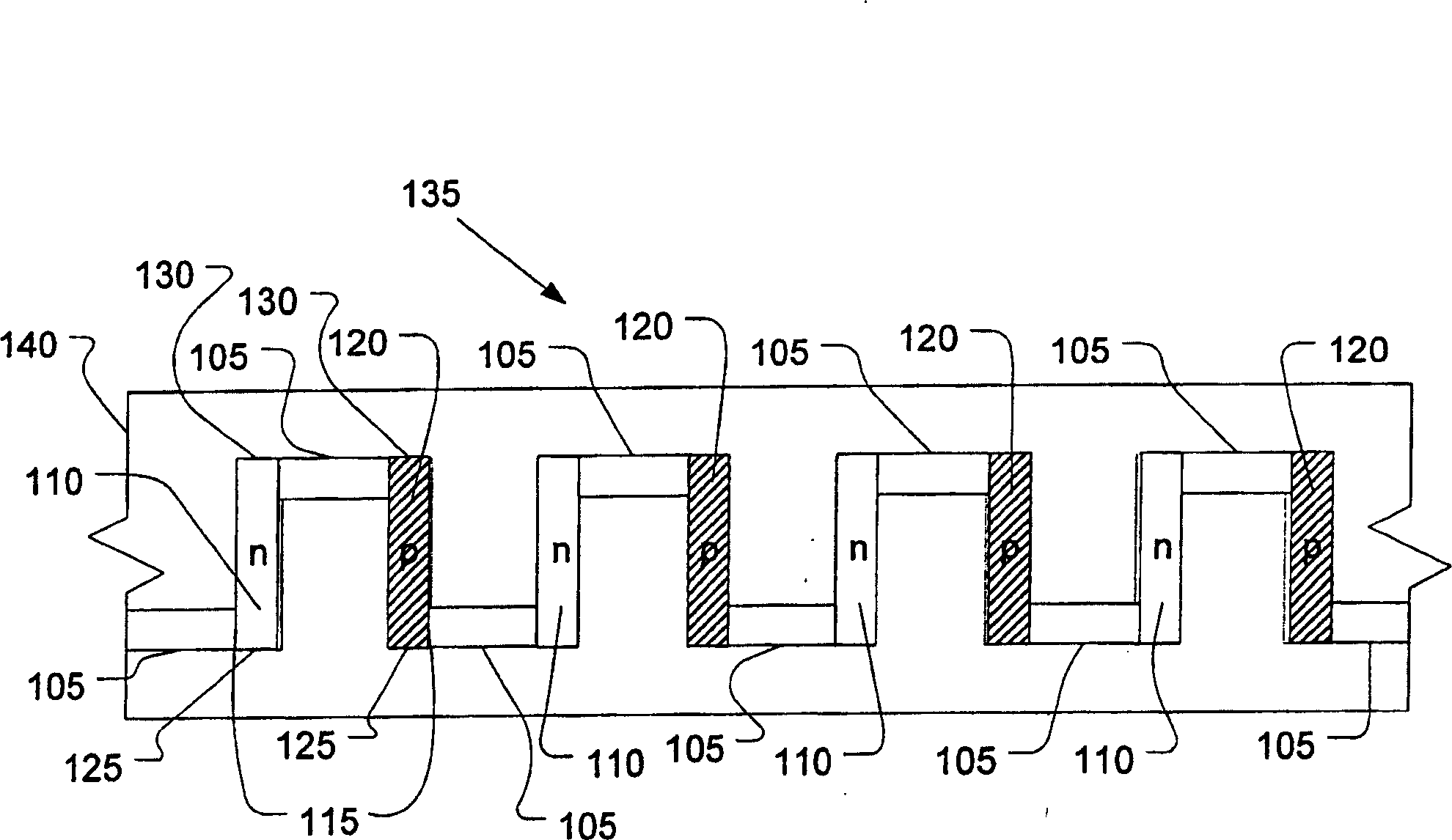
[0050] Disclosed herein are TE modules comprising: pairs of sputter-deposited thin-film thermal elements; and conductive components interconnecting the thermal elements in series or in series-parallel. Also disclosed is a TE power device formed from a plurality of TE couples, such as an array of TE couples, wherein the thin film thermal element has a thickness greater than at least about 20 cm -1 Or a L / A ratio greater than about 100 cm-1, with certain embodiments having an L / A ratio greater than 1000, 10,000, or even higher.

[0051] Unless otherwise indicated, all numbers expressing amounts of ingredients, properties such as L and A values, thicknesses, power levels, etc. used in the specification and claims are to be understood as being modified by the term "about", whether explicitly stated or not. Accordingly, unless expressly indicated to the contrary, the numerical parameters set forth are approximations.

[0052] exist Figure 2a is shown for forming the disclosed TE...


PUM


Abstract

High performance thin film thermoelectric couples and methods of making the same are disclosed. Such couples allow fabrication of at least microwatt to watt-level power supply devices operating at voltages greater than one volt even when activated by only small temperature differences.

Description

[0001] Statement of Government Support [0002] This invention was made with Government support under Contract DE AC0676RLO1830 awarded by the US Department of Energy. The government has certain rights in this invention. [0003] Cross References to Related Applications [0004] This application is a continuation-in-part of co-pending U.S. Patent Application Serial No. 10 / 726,744, filed December 2, 2003, and 10 / 727,062, filed December 2, 2003, and claims the benefits of The benefit of U.S. Provisional Patent Application No. 60 / 558,298 filed on March 30. technical field [0005] The present disclosure relates to thermoelectric devices, and materials and methods of making and using the same to produce efficient thermoelectric devices. Background technique [0006] The increasing use of portable electronic devices has driven research in the field of portable generators. Thermoelectric (TE) power sources have been found to be particularly useful. A TE power supply typically...

Claims


Application Information

Patent Timeline
Patent Type & Authority Applications(China)
IPC IPC(8): H01L35/30H01L35/08H01L35/16
CPCH01L35/16H01L35/08H10N10/817H10N10/852
Inventor 拉里·C·奥尔森约翰·G·德斯蒂斯彼得·M·马丁约翰·W·约翰斯通蒂莫西·J·彼得斯
Owner BATTELLE MEMORIAL INST
Why Eureka
Try Eureka