Dust detection device and electric dust collector mounted with the same

A dust detection and dust technology, applied in vacuum cleaners, cleaning equipment, household appliances, etc., can solve problems such as dust size difficulties

Active Publication Date: 2007-01-10
PANASONIC CORP
View PDF1 Cites 16 Cited by
  • Summary
  • Abstract
  • Description
  • Claims
  • Application Information

AI Technical Summary

Problems solved by technology

Therefore, it will be very difficult to correctly detect dust sizes that vary so much

Method used


Image

  • Dust detection device and electric dust collector mounted with the same
  • Dust detection device and electric dust collector mounted with the same
  • Dust detection device and electric dust collector mounted with the same

Examples


Embodiment 1

[0026] Embodiment 1 of the present invention will be described below with reference to the accompanying drawings. Here, the same constituent elements as those in the above existing unit are assigned the same symbols, and their detailed descriptions are omitted.

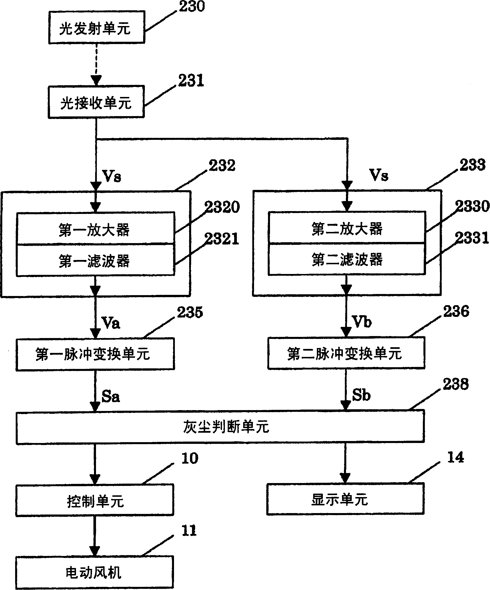
[0027] figure 1 It is a block diagram of the dust detection device in the electric vacuum cleaner according to Embodiment 1 of the present invention. exist figure 1 Among them, 230 and 231 are the light-emitting unit and the light-receiving unit that play the role of dust detection components, the light-emitting unit 230 is used to emit light into the air channel through which the dust flows, and the light-receiving unit 231 is used to receive light from the light-emitting unit 230 output light, and output a signal corresponding to the amount of light received. The light emitting unit 230 and the light receiving unit 231 are disposed opposite to each other in the air passage through which the dust flows. The sig...

Embodiment 2

[0039] Embodiment 2 of the present invention will be described below with reference to the accompanying drawings. In addition, for the same components as those of the conventional unit and the above Embodiment 1, only the same symbols are attached here, and the repeated description thereof is omitted.

[0040] Figure 5 It is a block diagram of an electric vacuum cleaner dust detection device in Embodiment 2 of the present invention. The difference from Embodiment 1 is that the setting of the second amplifying unit 233 is different, the output signal Va of the first amplifying unit 232 is input into the second amplifying unit 233, thereby performing secondary enlarge.

[0041] With such a configuration, since the input impedance of the amplifying unit to the output signal of the light receiving unit 231 can be increased compared with the first embodiment, the stability of the light receiving unit can be improved. In addition, the magnification factor when the second amplify...


PUM


Abstract

The present invention provides a kind of dust detection device that can detect fine dust according to the different sizes of the dust, which includes: a light emitting unit (dust detection unit 230) that emits light into the air channel through which the dust flows; A light receiving unit (dust detection unit 231) that receives light from the light emitting unit (230) and outputs a signal corresponding to the amount of light received; and amplifying units (232, 233) that amplify the signal from the light receiving unit (231). The amplifying unit (232, 233) has a plurality of magnifications corresponding to the size of the dust, so that a dust detection device capable of detecting dust containing fine dust according to the size of the dust can be provided.

Description

[0001] technology area [0002] The present invention relates to a dust detection device for detecting dust passing through an air passage in an electric vacuum cleaner and an electric vacuum cleaner equipped with the same. Background technique [0003] Among existing dust detection devices, there is a dust detection device used in electric vacuum cleaners as described below. [0004] The composition of this existing dust detection device is as follows: Figure 6 and Figure 7 shown in . exist Figure 6 and Figure 7 Among them, the light emitting unit 230 emits light into the air passage through which the dust flows, and the light receiving unit 231 receives the light emitted from the light emitting unit 230 and outputs a signal corresponding to the received light amount. The light emitting unit 230 and the light receiving unit 231 are oppositely arranged on both sides of the air channel through which the dust flows (hereinafter, the light emitting unit 230 and the light r...

Claims


Application Information

Patent Timeline
Patent Type & Authority Applications(China)
IPC IPC(8): A47L9/00A47L5/12
Inventor 伊藤昭人大岛裕夫上野圣一妹尾裕之
Owner PANASONIC CORP
Why Eureka
Try Eureka