
Laser scanning unit for splitting multiple light beams in a tandem image forming apparatus

A technology of laser scanning and imaging equipment, which is applied to equipment, optical components, and electrical recording technology using charge graphics, and can solve problems that hinder the ability of small series laser scanning units

Inactive Publication Date: 2007-01-10
SAMSUNG ELECTRONICS CO LTD
View PDF0 Cites 2 Cited by
  • Summary
  • Abstract
  • Description
  • Claims
  • Application Information

AI Technical Summary

Problems solved by technology

These requirements hamper the ability to develop small tandem laser scanning units

Method used


Image

  • Laser scanning unit for splitting multiple light beams in a tandem image forming apparatus
  • Laser scanning unit for splitting multiple light beams in a tandem image forming apparatus
  • Laser scanning unit for splitting multiple light beams in a tandem image forming apparatus

Examples


Embodiment Construction

[0031] Matters defined in the description, such as specific configurations and elements, are intended to assist in a comprehensive understanding of the embodiments of the present invention. Accordingly, those of ordinary skill in the art will recognize that various changes and modifications of the embodiments described herein can be made without departing from the scope and spirit of the invention. Also, descriptions of well-known functions and constructions are omitted for clarity and conciseness.

[0032] Exemplary embodiments of the present invention will now be described in detail with reference to the accompanying drawings.

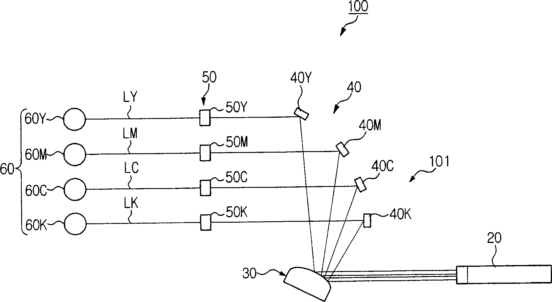
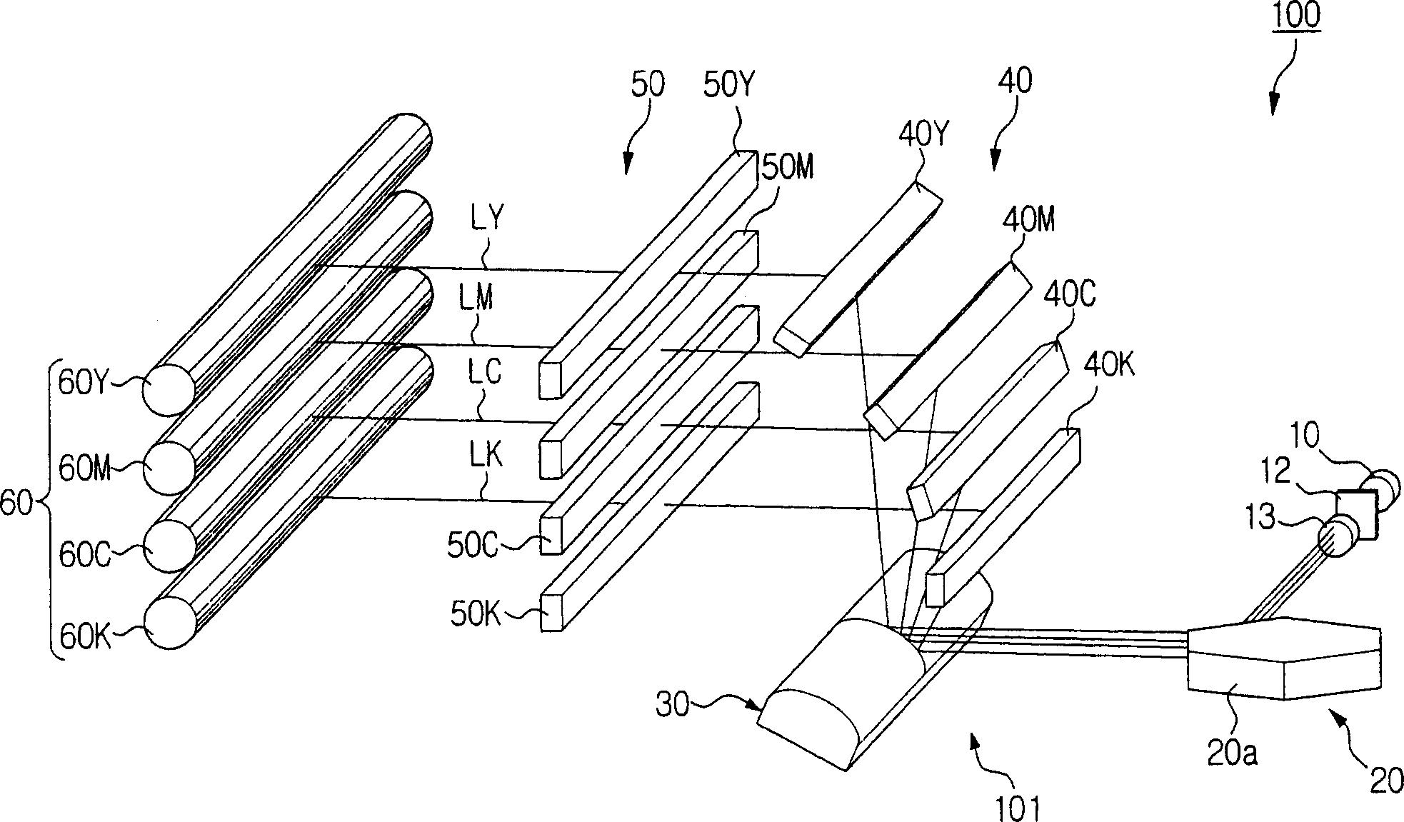
[0033] figure 2 is a schematic diagram of a laser scanning unit according to an exemplary embodiment of the present invention, image 3 Yes figure 2 Perspective view of the laser scanning unit shown. Referring to the drawings, a laser scanning unit 100 according to an exemplary embodiment of the present invention includes a light source 10 , a ...


PUM


Abstract

A laser scanning unit for an image forming apparatus includes a light source for producing and projecting light beams, a polygon mirror for deflecting the light beams, a beam splitter for splitting the light beams deflected by the polygon mirror, and an image forming lens arrangement for compensating for aberration of the light beams split by the splitter. The beam splitter has a convex cylindrical mirror and a concave cylindrical mirror, which are paired with each other. The configuration of the splitter allows a more compact arrangement.

Description

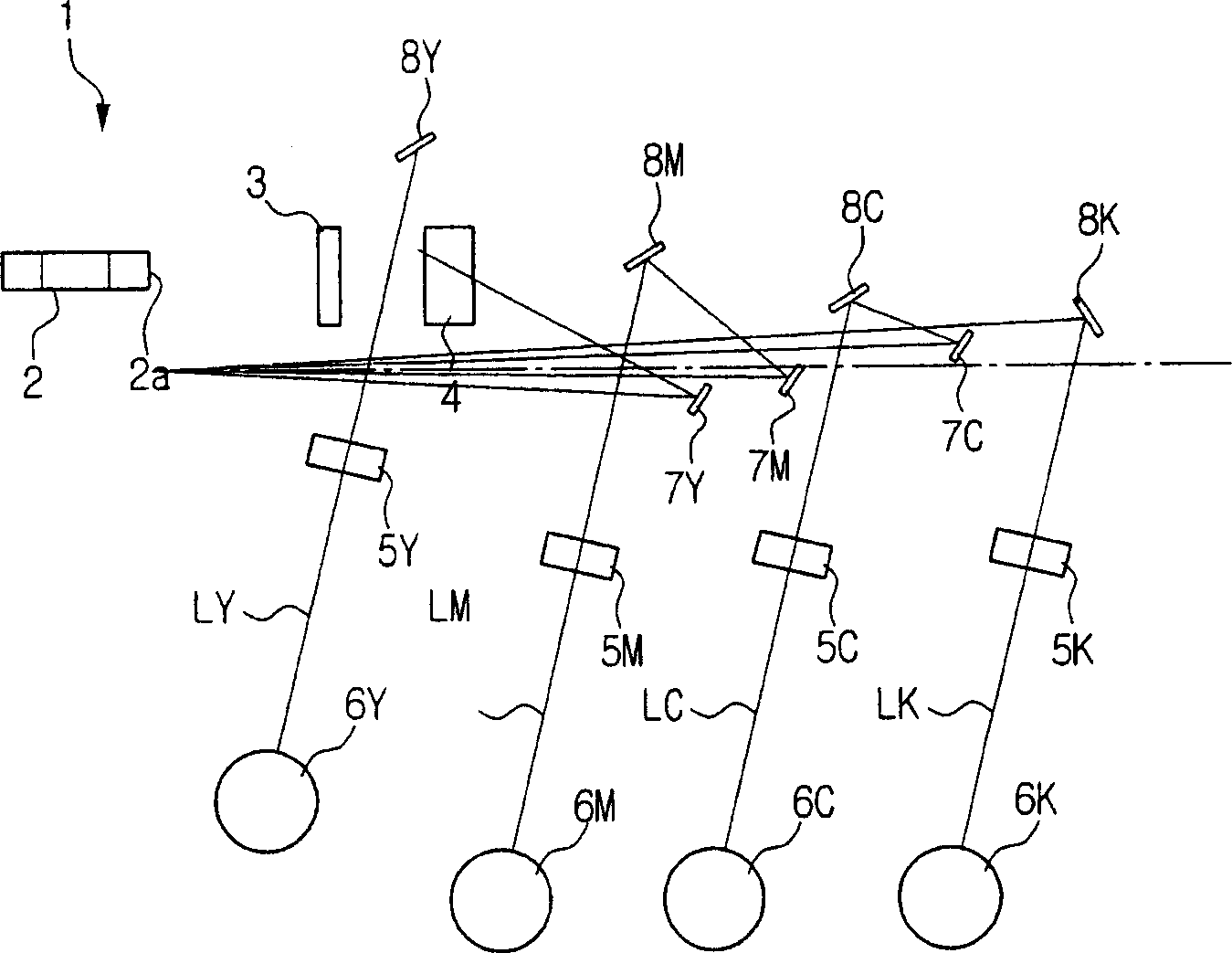
technical field [0001] The invention relates to a laser scanning unit. More specifically, the present invention relates to a compact laser scanning unit with improved ability to split multiple beams in a tandem imaging device. Background technique [0002] In tandem imaging devices (eg, imaging devices such as color laser printers, color digital copiers, etc.), images are formed by exposing multiple photoconductors scanned with multiple laser beams instead of a single laser beam to speed up device operation. When forming a color image by laser scanning, generally four photoconductors (for example, Y (yellow), M (magenta), C (cyan), and K (black)) are required. In a tandem scanning optical system for forming images on four photoconductors, a plurality of light beams are generally made incident on a polygon mirror at different oblique angles. The polygon mirror scans the light beam in the main scanning direction, and then separates the optical paths in the sub-scanning direc...

Claims


Application Information

Patent Timeline
Patent Type & Authority Applications(China)
IPC IPC(8): G02B26/12G03G15/00
CPCG02B26/123G03G15/04B41J2/473G02B26/124G03G15/0409
Inventor 金然奎
Owner SAMSUNG ELECTRONICS CO LTD
Learn More